LEDG[7] | PIN_ AA24 | LED Green[7] |
|
|
|
LEDG[8] | PIN_ AC14 | LED Green[8] |
|
|
|
Table 5.3. Pin assignments for the LEDs.
5.3 Using the 7-segment Displays
The
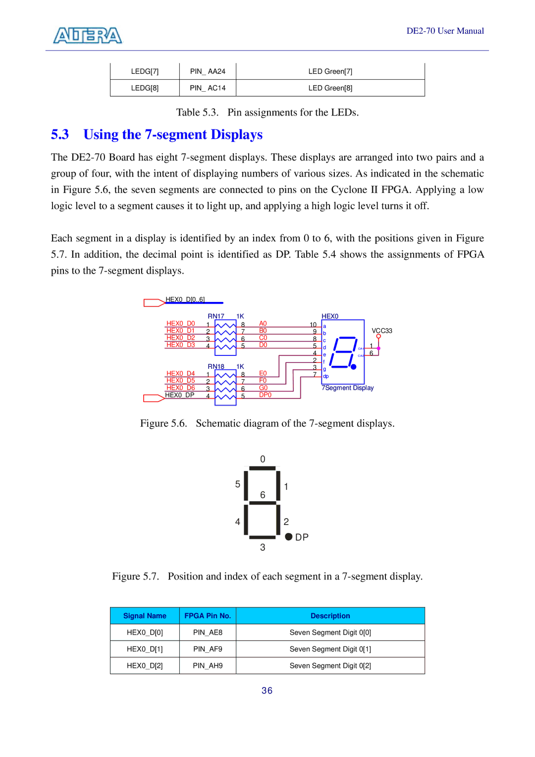
Each segment in a display is identified by an index from 0 to 6, with the positions given in Figure
5.7.In addition, the decimal point is identified as DP. Table 5.4 shows the assignments of FPGA pins to the
HEX0_D[0..6] |
|
|
|
HEX0_D0 | RN17 | 1K | A0 |
1 | 8 | ||
HEX0_D1 | 2 | 7 | B0 |
HEX0_D2 | 3 | 6 | C0 |
HEX0_D3 | 4 | 5 | D0 |
HEX0_D4 | RN18 | 1K | E0 |
1 | 8 | ||
HEX0_D5 | 2 | 7 | F0 |
HEX0_D6 | 3 | 6 | G0 |
HEX0_DP | 4 | 5 | DP0 |
10 9 8 5 4 2 3 7
HEX0
a b c d e f g dp
7Segment
VCC33
CA1 | 1 |
CA2 | 6 |
Display | |
Figure 5.6. Schematic diagram of the 7-segment displays.
0
51
6
4 2
![]()
![]()
![]() DP 3
DP 3
Figure 5.7. Position and index of each segment in a 7-segment display.
Signal Name | FPGA Pin No. | Description |
|
|
|
HEX0_D[0] | PIN_AE8 | Seven Segment Digit 0[0] |
|
|
|
HEX0_D[1] | PIN_AF9 | Seven Segment Digit 0[1] |
|
|
|
HEX0_D[2] | PIN_AH9 | Seven Segment Digit 0[2] |
|
|
|
36