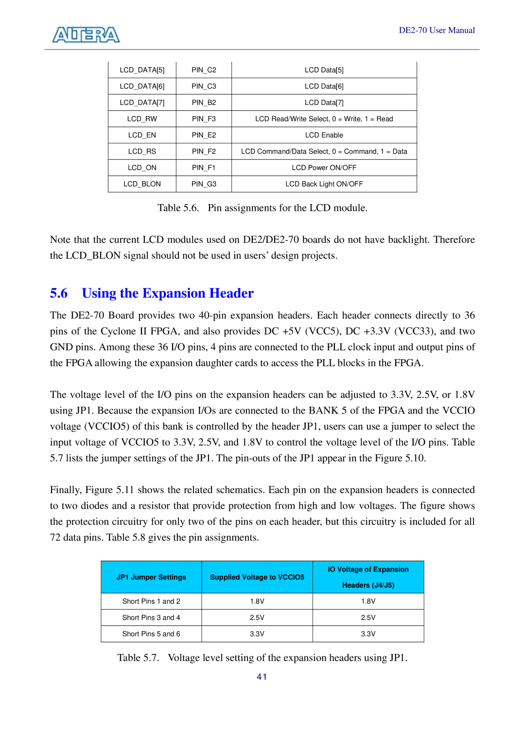
LCD_DATA[5] | PIN_C2 | LCD Data[5] |
|
|
|
LCD_DATA[6] | PIN_C3 | LCD Data[6] |
|
|
|
LCD_DATA[7] | PIN_B2 | LCD Data[7] |
|
|
|
LCD_RW | PIN_F3 | LCD Read/Write Select, 0 = Write, 1 = Read |
|
|
|
LCD_EN | PIN_E2 | LCD Enable |
|
|
|
LCD_RS | PIN_F2 | LCD Command/Data Select, 0 = Command, 1 = Data |
|
|
|
LCD_ON | PIN_F1 | LCD Power ON/OFF |
|
|
|
LCD_BLON | PIN_G3 | LCD Back Light ON/OFF |
|
|
|
Table 5.6. Pin assignments for the LCD module.
Note that the current LCD modules used on
5.6 Using the Expansion Header
The
The voltage level of the I/O pins on the expansion headers can be adjusted to 3.3V, 2.5V, or 1.8V using JP1. Because the expansion I/Os are connected to the BANK 5 of the FPGA and the VCCIO voltage (VCCIO5) of this bank is controlled by the header JP1, users can use a jumper to select the input voltage of VCCIO5 to 3.3V, 2.5V, and 1.8V to control the voltage level of the I/O pins. Table 5.7 lists the jumper settings of the JP1. The
Finally, Figure 5.11 shows the related schematics. Each pin on the expansion headers is connected to two diodes and a resistor that provide protection from high and low voltages. The figure shows the protection circuitry for only two of the pins on each header, but this circuitry is included for all 72 data pins. Table 5.8 gives the pin assignments.
JP1 Jumper Settings | Supplied Voltage to VCCIO5 | IO Voltage of Expansion | |
Headers (J4/J5) | |||
|
| ||
|
|
| |
Short Pins 1 and 2 | 1.8V | 1.8V | |
|
|
| |
Short Pins 3 and 4 | 2.5V | 2.5V | |
|
|
| |
Short Pins 5 and 6 | 3.3V | 3.3V | |
|
|
|
Table 5.7. Voltage level setting of the expansion headers using JP1.
41