5.5 Using the LCD Module
The LCD module has
| Q1 | 8050 | Q2 | 8550 |
|
|
|
|
|
| C6 |
VCC5 |
|
|
| R34 | 1u |
|
|
|
|
| |
VCC43 |
|
|
| 680 |
|
|
|
|
|
| |
LCD_ON | R35 | 680 |
| Q3 |
|
|
|
|
| 8050 |
|
LCD_D[0..7] |
|
|
|
| VCC43 |
| Q4 | 8550 |
|
|
|
|
|
|
|
|
|
|
|
|
|
|
|
|
|
|
|
|
|
|
|
|
|
|
|
|
|
|
|
|
|
| ||||||
|
|
|
|
|
|
|
|
|
|
|
|
|
|
|
|
|
|
|
|
|
|
|
|
|
|
|
|
|
|
|
|
|
|
|
|
| ||||||||||||
|
|
|
|
|
|
|
|
|
|
|
|
|
|
|
|
|
|
|
|
|
|
|
|
|
|
|
|
|
|
|
|
|
|
|
|
|
|
|
|
|
|
| ||||||
|
|
|
|
|
|
|
|
|
| R36 |
|
|
|
|
|
|
|
|
|
|
|
|
|
|
|
|
|
|
|
|
|
|
|
|
|
|
|
|
|
|
|
|
|
| ||||
|
|
|
|
|
|
|
|
|
|
|
|
|
|
|
|
|
|
|
|
|
|
|
|
|
|
|
|
|
|
|
|
|
|
|
|
|
|
|
|
|
|
|
| |||||
|
|
|
|
|
|
|
|
|
|
|
|
|
|
|
|
|
|
|
|
|
|
|
|
|
|
|
|
|
|
|
|
|
|
|
|
|
|
|
|
| TNO LCCD |
|
|
|
|
| ||
|
|
|
|
|
|
|
|
|
|
|
|
| 680 |
| LLCBD |
| 7LCDD |
| 6LCDD |
| 5DDCL |
| 4LCDD |
| 3LCDD |
| 2LCDD |
| 1LCDD |
| 0LCDD |
| ENLCD |
| WLCRD |
| SLCRD |
|
| CVCLCD | ||||||||
|
|
|
|
|
|
|
|
|
|
|
|
|
|
|
|
|
|
|
|
|
|
|
|
|
|
| ||||||||||||||||||||||
LCD_BLON R37 | 680 |
|
|
|
|
|
|
| 8050 |
|
|
|
|
|
|
|
|
|
|
|
|
|
| |||||||||||||||||||||||||
|
|
|
|
|
|
| Q5 |
|
|
|
|
|
|
|
|
|
|
|
|
|
|
|
|
|
|
|
|
|
|
|
|
|
|
|
|
|
|
|
|
|
| |||||||
|
|
|
|
|
|
|
|
|
|
|
|
|
|
| 16 |
| 15 |
| 14 |
| 13 |
| 12 |
| 11 |
| 10 |
| 9 |
| 8 |
| 7 |
| 6 |
| 5 |
| 4 |
| 3 |
| 2 |
| 1 |
| ||
|
|
|
|
|
|
|
|
|
|
|
|
|
|
|
|
|
|
|
|
|
|
|
|
|
|
|
|
|
|
| ||||||||||||||||||
|
|
|
|
|
|
|
|
|
|
|
|
|
|
|
|
|
|
|
|
|
|
|
|
|
|
|
|
|
|
| ||||||||||||||||||
|
|
|
|
|
|
| DIS1 |
|
|
|
|
|
|
|
|
|
|
|
|
|
|
|
|
|
| |||||||||||||||||||||||
|
|
|
|
|
|
|
|
|
|
|
|
|
|
|
|
|
|
|
|
|
|
|
|
|
|
|
|
|
|
|
|
|
|
|
|
|
|
|
|
|
|
| ||||||
|
|
|
|
|
|
|
|
|
|
|
|
|
|
|
| |||||||||||||||||||||||||||||||||
|
|
|
|
|
|
|
|
|
|
|
|
|
|
| D BL 7 6 5 4 3 2 1 0 EN N D D D D D D D D G |
| WR SR TN CVC DN O G C | |||||||||||||||||||||||||||||||
|
|
|
|
|
|
|
|
|
|
|
|
|
|
|
| |||||||||||||||||||||||||||||||||
|
|
|
|
| 2 |
| X | 16 DIGIT LCD |
| |||||||||||||||||||||||||||||||||||||||
|
|
|
|
|
|
|
|
|
|
|
|
|
|
|
|
|
|
|
|
|
|
|
|
|
|
|
|
|
|
|
|
|
|
|
|
|
|
|
|
|
|
|
|
|
|
|
|
|
VCC43
R38 1K
R39 47
|
|
|
| ||
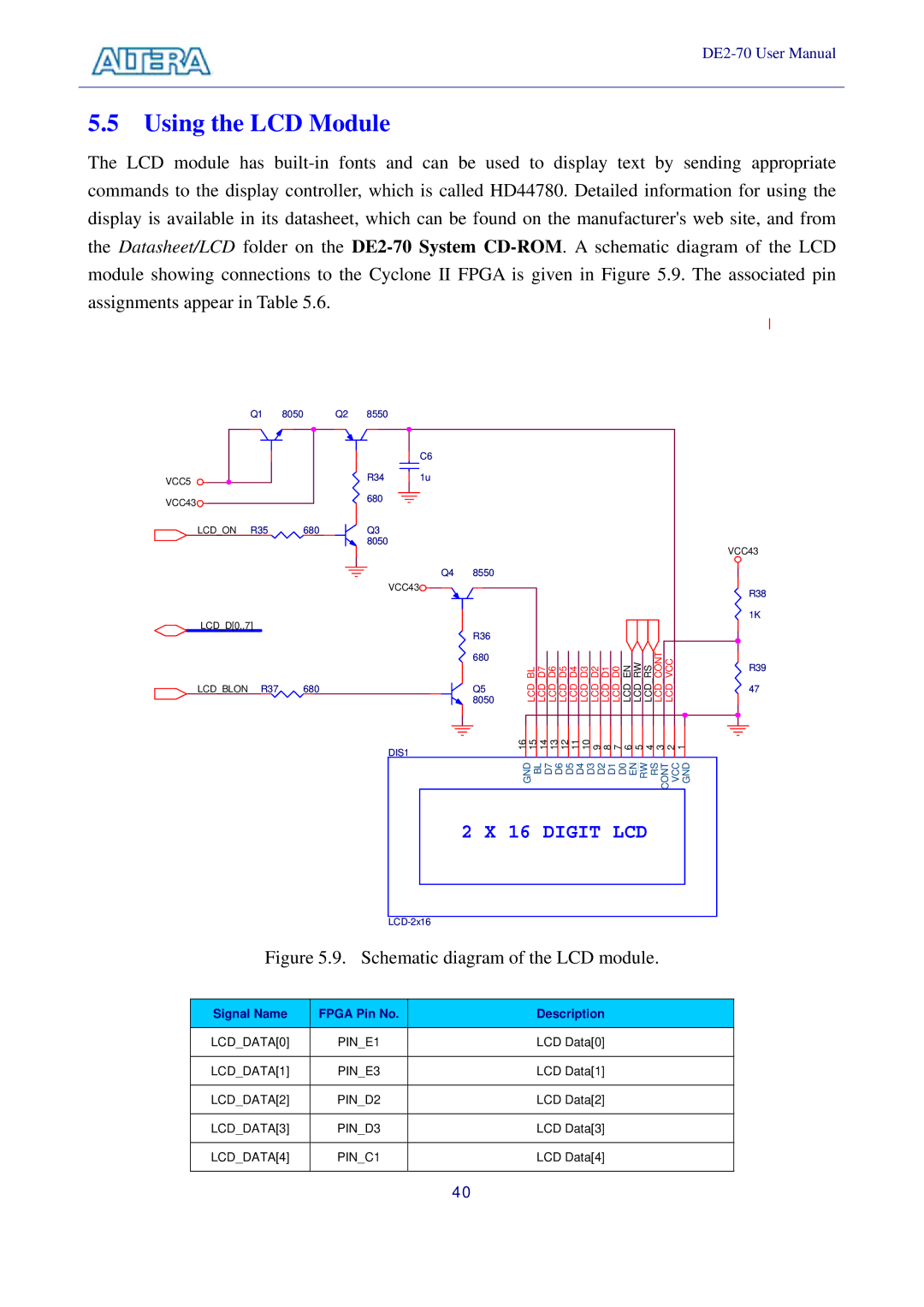
Figure 5.9. Schematic diagram of the LCD module. |
| ||||
|
|
|
|
| |
Signal Name | FPGA Pin No. |
| Description |
| |
|
|
|
|
| |
LCD_DATA[0] | PIN_E1 |
| LCD Data[0] |
| |
|
|
|
|
| |
LCD_DATA[1] | PIN_E3 |
| LCD Data[1] |
| |
|
|
|
|
| |
LCD_DATA[2] | PIN_D2 |
| LCD Data[2] |
| |
|
|
|
|
| |
LCD_DATA[3] | PIN_D3 |
| LCD Data[3] |
| |
|
|
|
|
| |
LCD_DATA[4] | PIN_C1 |
| LCD Data[4] |
| |
|
|
|
|
|
|
40