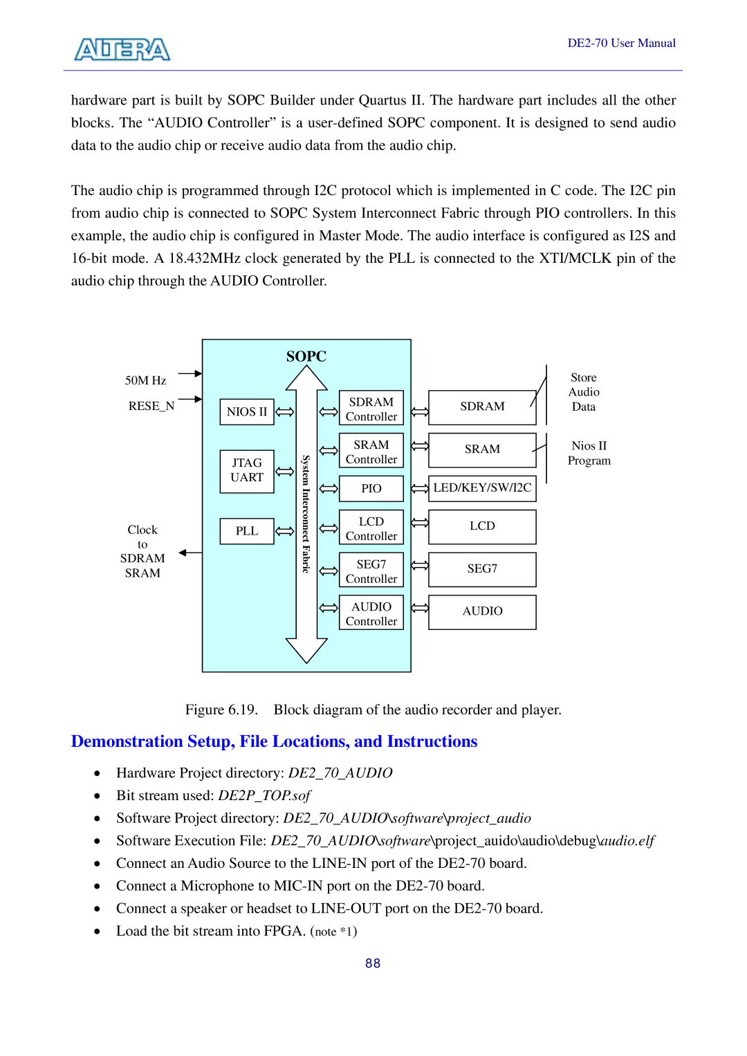
hardware part is built by SOPC Builder under Quartus II. The hardware part includes all the other blocks. The “AUDIO Controller” is a
The audio chip is programmed through I2C protocol which is implemented in C code. The I2C pin from audio chip is connected to SOPC System Interconnect Fabric through PIO controllers. In this example, the audio chip is configured in Master Mode. The audio interface is configured as I2S and
|
| SOPC |
|
|
|
50M Hz |
|
|
|
| Store |
RESE_N |
|
| SDRAM | SDRAM | Audio |
NIOS II |
| Data | |||
|
| Controller |
|
| |
|
|
|
|
| |
| JTAG |
| SRAM | SRAM | Nios II |
| System | Controller |
| Program | |
| UART | PIO | LED/KEY/SW/I2C |
| |
|
| Interconnect |
| ||
Clock | PLL | LCD | LCD |
| |
Controller |
| ||||
|
| ||||
to |
| Fabric |
|
|
|
SDRAM |
| SEG7 | SEG7 |
| |
SRAM |
|
| |||
|
| Controller |
|
| |
|
|
|
|
| |
|
|
| AUDIO | AUDIO |
|
|
|
| Controller |
| |
|
|
|
|
|
Figure 6.19. Block diagram of the audio recorder and player.
Demonstration Setup, File Locations, and Instructions
•Hardware Project directory: DE2_70_AUDIO
•Bit stream used: DE2P_TOP.sof
•Software Project directory: DE2_70_AUDIO\software\project_audio
•Software Execution File: DE2_70_AUDIO\software\project_auido\audio\debug\audio.elf
•Connect an Audio Source to the
•Connect a Microphone to
•Connect a speaker or headset to
•Load the bit stream into FPGA. (note *1)
88