DE2-70 User Manual
5.9 RS-232 Serial Port
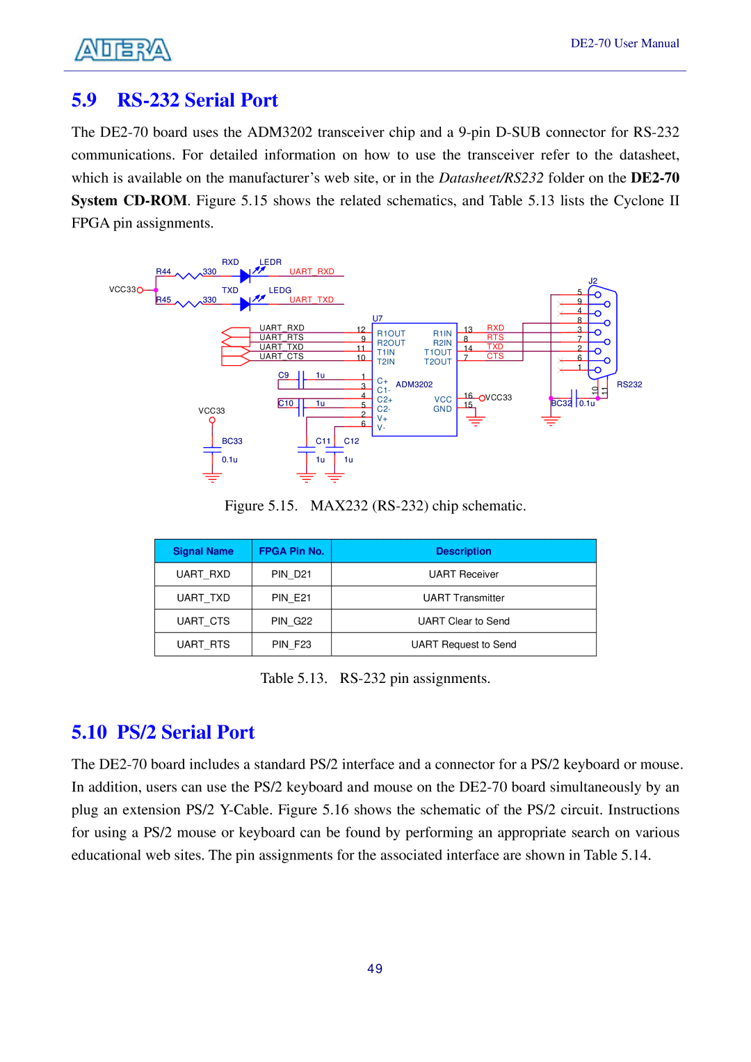
The DE2-70 board uses the ADM3202 transceiver chip and a 9-pin D-SUB connector for RS-232 communications. For detailed information on how to use the transceiver refer to the datasheet, which is available on the manufacturer’s web site, or in the Datasheet/RS232 folder on the DE2-70 System CD-ROM. Figure 5.15 shows the related schematics, and Table 5.13 lists the Cyclone II FPGA pin assignments.
| RXD | LEDR | |
R44 | 330 | UART_RXD |
VCC33 | TXD | LEDG | |
R45 | 330 | UART_TXD |
| | UART_RXD | |
| | UART_RTS | |
| | UART_TXD | |
| | UART_CTS | |
| | C9 | 1u |
| VCC33 | C10 | 1u |
| | |
| BC33 | | C11 |
| 0.1u | | 1u |
| U7 | | |
| R1OUT | R1IN |
| R2OUT | R2IN |
| T1IN | | T1OUT |
| T2IN | | T2OUT |
| C+ | ADM3202 |
| C1- |
| | VCC |
| C2+ | |
| C2- | | GND |
| V+ | | |
| V- | | |
| | | |
13RXD
8RTS
14TXD
7CTS
16VCC33
| J2 |
| 5 |
| 9 |
| 4 |
| 8 |
| 3 |
| 7 |
| 2 |
| 6 |
| 1 |
| 10 11 |
BC32 | 0.1u |
Figure 5.15. MAX232 (RS-232) chip schematic.
Signal Name | FPGA Pin No. | Description |
| | |
UART_RXD | PIN_D21 | UART Receiver |
| | |
UART_TXD | PIN_E21 | UART Transmitter |
| | |
UART_CTS | PIN_G22 | UART Clear to Send |
| | |
UART_RTS | PIN_F23 | UART Request to Send |
| | |
Table 5.13. RS-232 pin assignments.
5.10 PS/2 Serial Port
The DE2-70 board includes a standard PS/2 interface and a connector for a PS/2 keyboard or mouse. In addition, users can use the PS/2 keyboard and mouse on the DE2-70 board simultaneously by an plug an extension PS/2 Y-Cable. Figure 5.16 shows the schematic of the PS/2 circuit. Instructions for using a PS/2 mouse or keyboard can be found by performing an appropriate search on various educational web sites. The pin assignments for the associated interface are shown in Table 5.14.
49