Installation
S35
STEERING LEVER
AUTOPILOT COMPUTER
POW ER PCB
TB1 TB2 TB3 | TB4 | TB5 |
|
| TB7 |
|
|
| REMOTE |
| |||||
|
|
|
| Gnd | |||
|
|
| TB6 | Lamp | Stbd | Port | |
|
|
|
|
|
|
| |
N O T E! | Ye l | Br n /W | Pn k/G |
| G rn |
Disregard th e co lor code |
| ||||
on the termi nal lab el . |
| h | r y |
|
|
|
| ||||
|
|
|
|
|
|
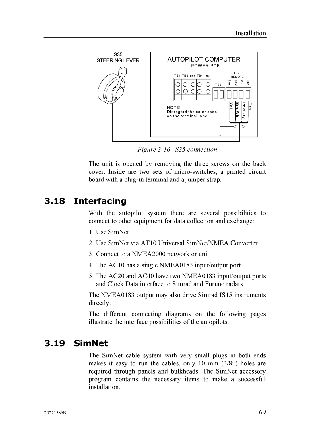
Figure 3-16 S35 connection
The unit is opened by removing the three screws on the back cover. Inside are two sets of
3.18Interfacing
With the autopilot system there are several possibilities to connect to other equipment for data collection and exchange:
1.Use SimNet
2.Use SimNet via AT10 Universal SimNet/NMEA Converter
3.Connect to a NMEA2000 network or unit
4.The AC10 has a single NMEA0183 input/output port.
5.The AC20 and AC40 have two NMEA0183 input/output ports and Clock Data interface to Simrad and Furuno radars.
The NMEA0183 output may also drive Simrad IS15 instruments directly.
The different connecting diagrams on the following pages illustrate the interface possibilities of the autopilots.
3.19SimNet
The SimNet cable system with very small plugs in both ends makes it easy to run the cables, only 10 mm (3/8”) holes are required through panels and bulkheads. The SimNet accessory program contains the necessary items to make a successful installation.
20221586B | 69 |