Simrad AP26 and AP27 Autopilots
Attach the ball joint to the tiller arm, and connect the transmitter rod to the ball joint at the rudder tiller arm.
Turn the helm wheel to set the rudder tiller arm to approximate centre position.
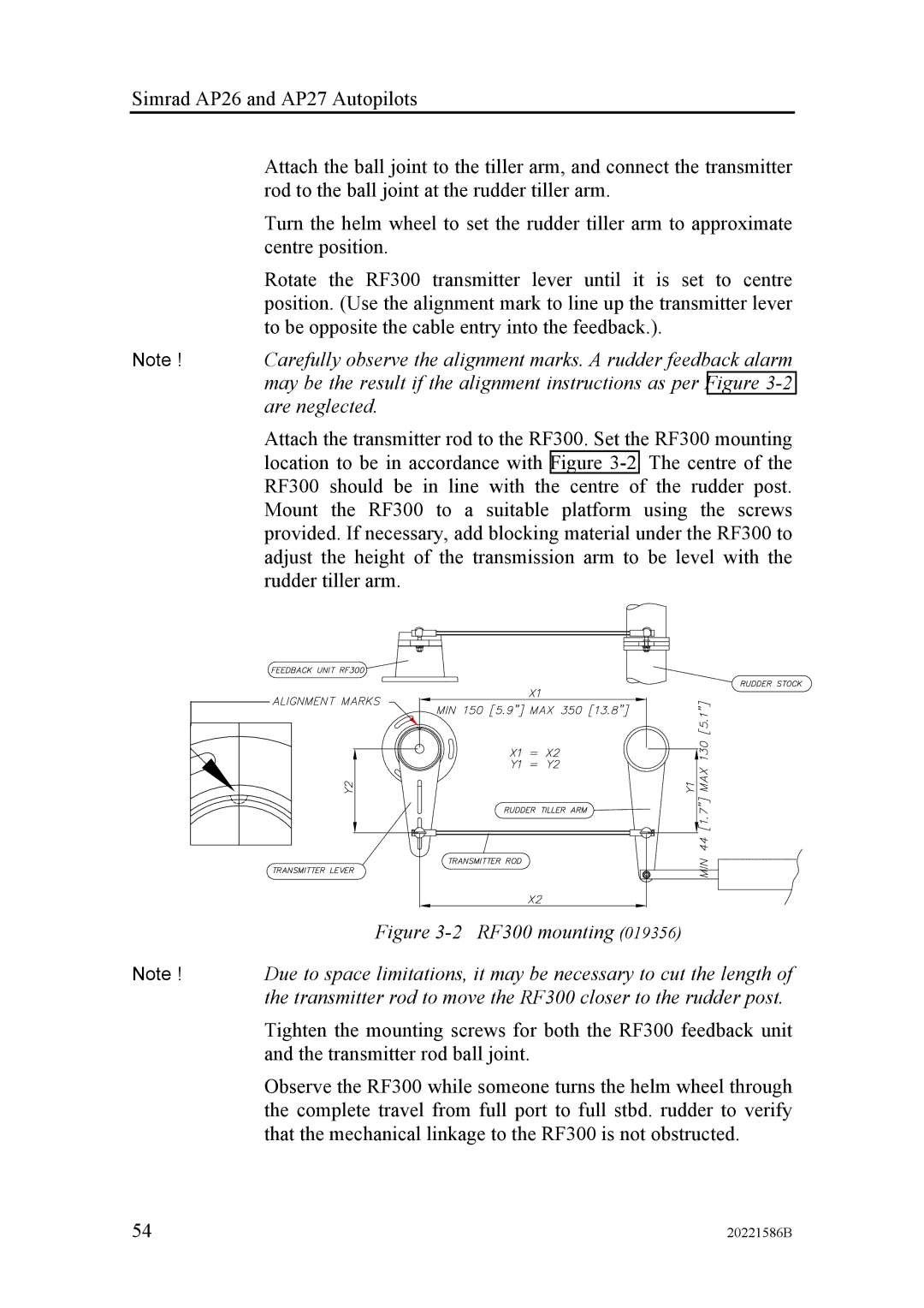
Rotate the RF300 transmitter lever until it is set to centre position. (Use the alignment mark to line up the transmitter lever to be opposite the cable entry into the feedback.).
Note ! Carefully observe the alignment marks. A rudder feedback alarm may be the result if the alignment instructions as per Figure
Attach the transmitter rod to the RF300. Set the RF300 mounting location to be in accordance with Figure
Figure 3-2 RF300 mounting (019356)
Note ! Due to space limitations, it may be necessary to cut the length of the transmitter rod to move the RF300 closer to the rudder post.
Tighten the mounting screws for both the RF300 feedback unit and the transmitter rod ball joint.
Observe the RF300 while someone turns the helm wheel through the complete travel from full port to full stbd. rudder to verify that the mechanical linkage to the RF300 is not obstructed.
54 | 20221586B |
