Simrad AP26 and AP27
This page is intentionally left blank
20221586B
Document revisions
Contents
Racing
Installation
Configuration and setup
115
Trouble shooting 118
General
How to use this manual
AP26 Basic system
System components
AP27 Control Unit
AP26 Control Unit
Autopilot Computer
RFC35 Electronic Fluxgate Compass optional
RF300 Rudder Feedback unit
Heading Sensors
RC36 Rate compass
Simrad RGC10 and RGC50 gyrocompasses
Nmea compass optional
FU25 Follow-Up Steering Lever
R3000X Remote Control
Optional equipment
JS10 Joystick
Overview
Operation
AP27 Front Panel
AP26
ON/OFF Standby mode
Flashing course knob icon
Alarms
Zero point setting
AP26 and AP27 with MSD50 Stern Drive Unit
Follow-Up steering FU
Non-Follow-Up steering NFU
Initial mode 1st press 2nd press
R3000X Remote Control NFU
JS10 Joystick NFU
Heading catch
Automatic Steering
TURN/DODGE/INFO button
Automatic control of steering parameters
Power boat
Sailboat
Manual Parameter Selection
Turn
Dodge in Auto
Navigating with the AP26 and AP27
Tacking in Auto mode
NAV
− NAV mode
Setting the waypoint arrival circle
Selecting a different Navigation source
Dodge in NAV
Wind vane steering
Tacking and gybing in Wind mode
Tack and gybe prevent
Gybing
Wind steering and navigation
Simrad AP26 and AP27 Autopilots
Racing
Operating in Windnav mode
Lock function
Multiple station system
Backlight
Standby Mode
User Set-up Menu
Alternating Course Knob Icon
Nav/Wind, Racing parameters
Nav/Wind
Layline Steering
VMG Optimizing
Manual select
Auto source update
Instrument Select
Source Select
Position
Water temperature
Compass
Navigation
Depth
Auto Mode
Course Adjust
DisLog
Wind response
NAV Mode
Wind Mode
Response
Auto mode
Standby mode
Info menu
True wind
Nav mode
Depth/Speed
Apparent wind
Nav data
Sea Temperature
Course knob icon
Track data
Info menu flowchart
Info menu and Main screen, active unit
Alternative mode screens in STBY, Auto and NAV
Info menu and Main Screen, inactive unit
Installation checklist
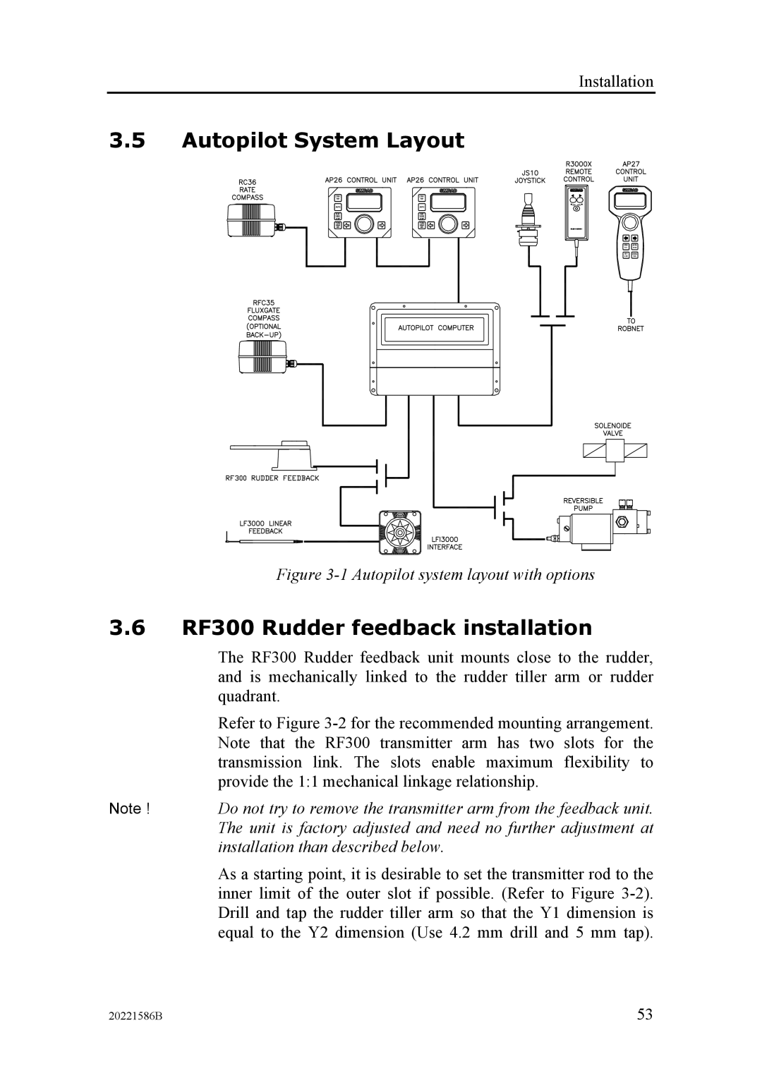
Installation
Unpacking and handling
Determine system configuration
Autopilot System Layout
RF300 Rudder feedback installation
RF300 mounting
Cable connections
Autopilot computer installation
Cable length Drive Unit Voltage
Grounding and RFI
Ground terminal
Hydraulic Pumps
Drive unit installation
Linear Drive Units
Previous Models of Drive Units
Connecting a reversible pump
Connecting a solenoid valve
Connecting a hydraulic linear drive
Do not over-tighten the mounting screws
Control unit installation
Panel mounting of AP26
Alternative panel mounting of AP26
Optional bracket mounting
ROBNET2 network cables
See note on
System
Cable pairs Color code Signal
AP27 connection
13 RC36 Rate Compass installation
20221586B
14 RFC35 connection
14 RFC35 Fluxgate Compass installation
17 S35 NFU Lever installation
15 R3000X Remote Control installation
16 JS10 Joystick
SimNet
Interfacing
SimNet network cables
SimNet power and termination
17 SimNet network, small system
19 SimNet/NMEA2000 network, medium system
20 Robnet2 and SimNet network
21 Robnet2, SimNet and Roblink network
Double Nmea input/output
Single Nmea input/output
Nmea Compass input
Nmea output on Port
Radar Clock/Data
25 IS15 Instrument installation
26 IS15 Instruments / Autopilot computer connection
27 LF3000 Linear Feedback
External Alarm
29 LF3000 mounting
30 LF3000/LFI3000 Mk2 connections
20221586B
First time turn on
Configuration and Setup
Description of Installation Settings
Installation Menu
Installation Menu Flow Chart
Language selection
Dockside settings
Drive unit voltage
Boat type
Rudder Feedback Calibration
Rudder Test
Drive engage
Rudder Deadband
Wind setup
Minimum wind angle Racing
Minimum wind angle Normal
Tack angle Racing
Tack time Racing
Wind shift alarm limit Racing
Display units
Interface Settings
Sea Trial
Minimum rudder
Set Rudder zero
Compass calibration
Local magnetic and heading errors
Compass Offset
Wind damping
Wind Offset
Depth Offset
Automatic tuning
Transition Speed
Init NAV
Parameters
Tuning
Manual parameter adjust
106
Recall Autotuned?
Service Menu
SimNet and Nmea Data Screen
System Data Menu
INV
Nmea Port test AC hardware
SimNet setup
Group selection
SimNet gateway
Global SimNet reset
Backlight Illumination
Instance number
Final sea trial
Master Reset
Providing user training
114
Drive unit
Control unit
Rudder Feedback
Compass
Autopilot Computer
Exchange of software programme
Part of AP26 PCB
Autopilot Control Unit
Alarms
Trouble Shooting
User Setup2/Source select
Display readout Probable fault Recommended action
PCB
Acxx
Com. failure with Faulty Autopilot Check Robnet2 connectors
AP27 Control Unit
AP26 Control Unit
Autopilot Computers
Robnet2 cables
RFC35 Electronic Fluxgate Compass
RC36 Rate compass
RF300 Rudder Feedback Unit
Tools
SimNet cables and accessories
AP26 and AP27 Autopilot System
Technical Specifications
Instrument screen NMEA0183 messages and SimNet
128
AP27 Control Unit dimensions
Autopilot Computers
AC10/AC20 Autopilot computer Dimensions
RC36 Rate compass
RC36 Rate Compass Dimensions
RF300 Rudder Feedback
RFC35 Fluxgate compass
RF300 Rudder Feedback Dimensions
JS10 Joystick
R3000X Remote Control
10 FU25 Steering Lever
10 FU25 Steering Lever Dimensions
Nmea 0183, HDG, HDM, HDT
11 IS15 Rudder
11 IS15 Rudder Dimensions
Tests
IP protection
NMEA0183 messages and data overview for AC10, AC20, AC40
Nmea and SimNet messages
141
Information required to operate in Windn mode
143
Glossary
145
146
Index
148
149
150