Maintenance
Rudder Feedback Calibration
Make sure the RF300 is installed and aligned as pr. instruction in section 3.6 (or eventually section 3.27 for LF3000). This function enables you to compensate for any
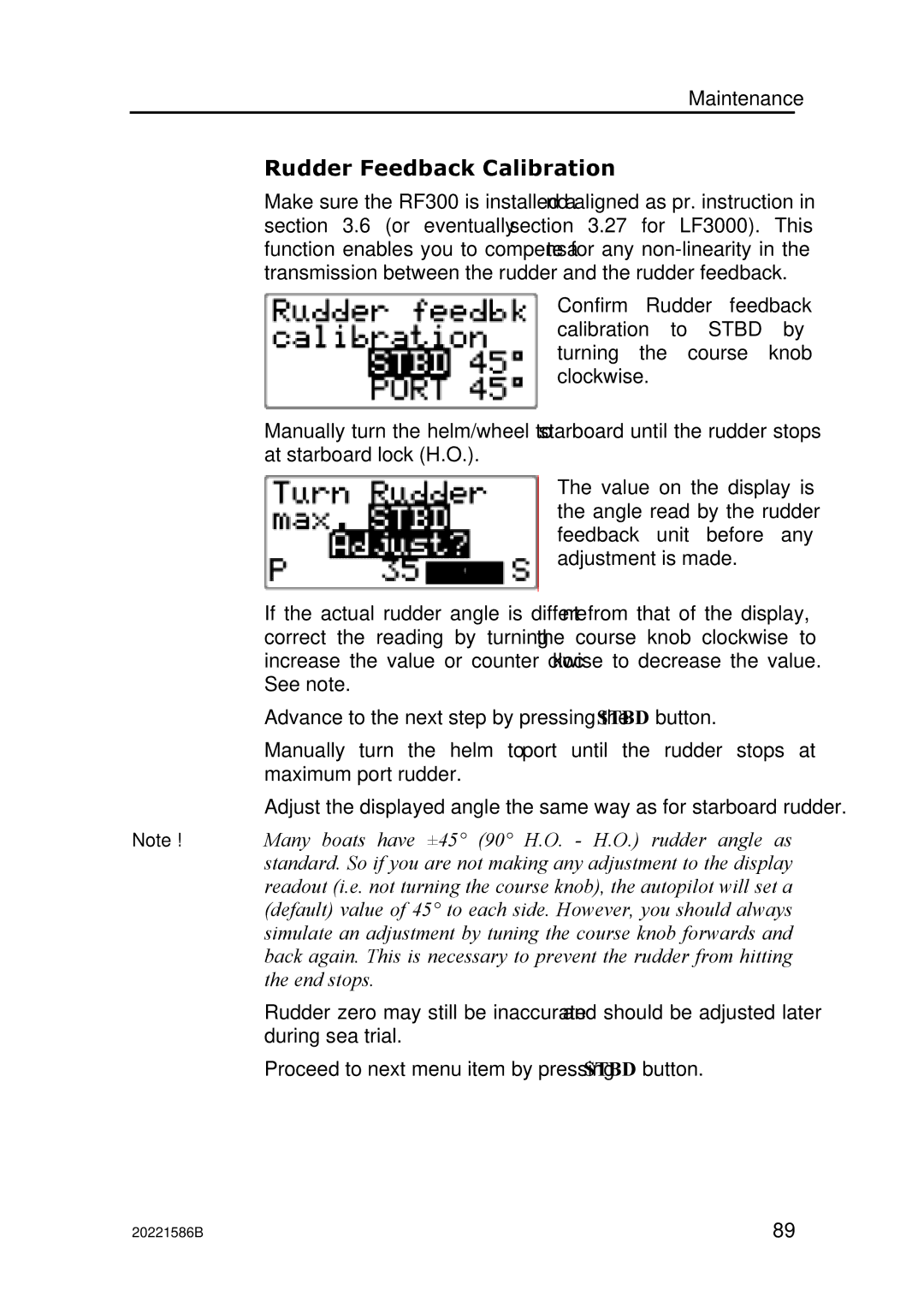
Confirm Rudder feedback calibration to STBD by turning the course knob clockwise.
Manually turn the helm/wheel to starboard until the rudder stops at starboard lock (H.O.).
The value on the display is the angle read by the rudder feedback unit before any adjustment is made.
If the actual rudder angle is different from that of the display, correct the reading by turning the course knob clockwise to increase the value or counter clockwise to decrease the value. See note.
Advance to the next step by pressing the STBD button.
Manually turn the helm to port until the rudder stops at maximum port rudder.
Adjust the displayed angle the same way as for starboard rudder.
Note ! Many boats have ±45° (90° H.O. - H.O.) rudder angle as standard. So if you are not making any adjustment to the display readout (i.e. not turning the course knob), the autopilot will set a (default) value of 45° to each side. However, you should always simulate an adjustment by tuning the course knob forwards and back again. This is necessary to prevent the rudder from hitting the end stops.
Rudder zero may still be inaccurate and should be adjusted later during sea trial.
Proceed to next menu item by pressing STBD button.
20221586B | 89 |