WARNING
Some components inside the power supply area are at AC voltage even when the On/Off switch is in the “Off” position. To avoid electric shock hazard, disconnect the line cord and load and wait two minutes before removing cover.
3.7.1 AC Input Connector
An IEC connector is provided on the rear panel for connecting the unit to the AC power source with an AC cord. The IEC connector also provides the safety ground connection while the AC cord is plugged into an appropriate AC receptacle.
3.7.2 AC Input Cord
Refer to Section 1.3.4 for details of the AC input cords recommended for the GENH750W mod- els.
WARNING
The AC input cord is the disconnect device of the power supply. The plug must be readily identifiable and accessible to the user. The AC input cord must be no longer than 3m.
3.8 TURN-ON CHECKOUT PROCEDURE
3.8.1 General
The following procedure ensures that the power supply is operational and may be used as a ba- sic incoming inspection check. Refer to
3.8.2 Prior to Operation
1.Ensure that the power supply is configured to the default setting:
–AC On/Off switch at Off position.
–Dip switch: All positions at Down (“Off”) position.
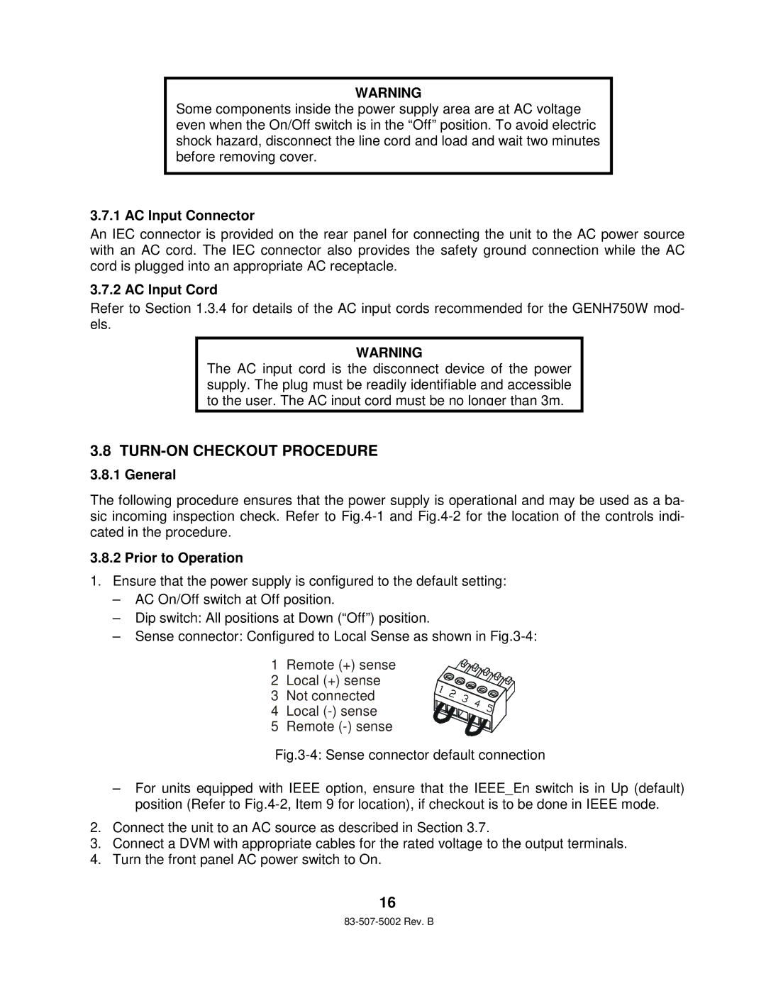
–Sense connector: Configured to Local Sense as shown in
1 Remote (+) sense
2 Local (+) sense
3 Not connected
4 Local
5 Remote
Fig.3-4: Sense connector default connection
–For units equipped with IEEE option, ensure that the IEEE_En switch is in Up (default) position (Refer to Fig.4-2, Item 9 for location), if checkout is to be done in IEEE mode.
2.Connect the unit to an AC source as described in Section 3.7.
3.Connect a DVM with appropriate cables for the rated voltage to the output terminals.
4.Turn the front panel AC power switch to On.
16