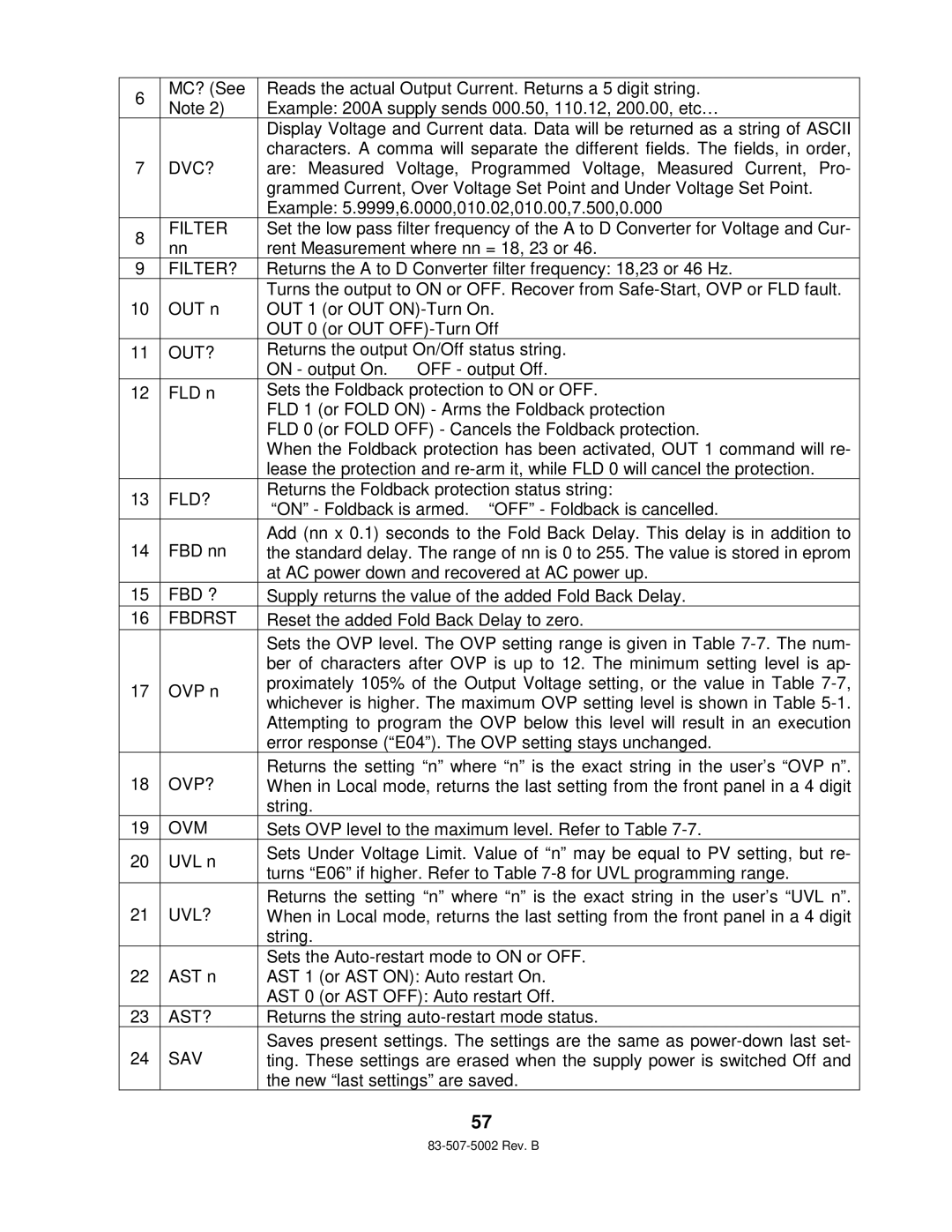
6 | MC? (See | Reads the actual Output Current. Returns a 5 digit string. | |
Note 2) | Example: 200A supply sends 000.50, 110.12, 200.00, etc… | ||
| |||
|
| Display Voltage and Current data. Data will be returned as a string of ASCII | |
|
| characters. A comma will separate the different fields. The fields, in order, | |
7 | DVC? | are: Measured Voltage, Programmed Voltage, Measured Current, Pro- | |
|
| grammed Current, Over Voltage Set Point and Under Voltage Set Point. | |
|
| Example: 5.9999,6.0000,010.02,010.00,7.500,0.000 | |
8 | FILTER | Set the low pass filter frequency of the A to D Converter for Voltage and Cur- | |
nn | rent Measurement where nn = 18, 23 or 46. | ||
| |||
9 | FILTER? | Returns the A to D Converter filter frequency: 18,23 or 46 Hz. | |
|
| Turns the output to ON or OFF. Recover from | |
10 | OUT n | OUT 1 (or OUT | |
|
| OUT 0 (or OUT | |
11 | OUT? | Returns the output On/Off status string. | |
|
| ON - output On. OFF - output Off. | |
12 | FLD n | Sets the Foldback protection to ON or OFF. | |
|
| FLD 1 (or FOLD ON) - Arms the Foldback protection | |
|
| FLD 0 (or FOLD OFF) - Cancels the Foldback protection. | |
|
| When the Foldback protection has been activated, OUT 1 command will re- | |
|
| lease the protection and | |
13 | FLD? | Returns the Foldback protection status string: | |
“ON” - Foldback is armed. “OFF” - Foldback is c ancelled. | |||
|
| ||
14 | FBD nn | Add (nn x 0.1) seconds to the Fold Back Delay. This delay is in addition to | |
the standard delay. The range of nn is 0 to 255. The value is stored in eprom | |||
|
| at AC power down and recovered at AC power up. | |
15 | FBD ? | Supply returns the value of the added Fold Back Delay. | |
16 | FBDRST | Reset the added Fold Back Delay to zero. | |
|
| Sets the OVP level. The OVP setting range is given in Table | |
|
| ber of characters after OVP is up to 12. The minimum setting level is ap- | |
17 | OVP n | proximately 105% of the Output Voltage setting, or the value in Table | |
whichever is higher. The maximum OVP setting level is shown in Table | |||
|
| ||
|
| Attempting to program the OVP below this level will result in an execution | |
|
| error response (“E04”). The OVP setting stays unchanged. | |
18 | OVP? | Returns the setting “n” where “n” is the exact stri ng in the user’s “OVP n”. | |
When in Local mode, returns the last setting from the front panel in a 4 digit | |||
|
| string. | |
19 | OVM | Sets OVP level to the maximum level. Refer to Table | |
20 | UVL n | Sets Under Voltage Limit. Value of “n” may be equal to PV setting, but re- | |
turns “E06” if higher. Refer to Table | |||
|
| ||
21 | UVL? | Returns the setting “n” where “n” is the exact stri ng in the user’s “UVL n”. | |
When in Local mode, returns the last setting from the front panel in a 4 digit | |||
|
| string. | |
|
| Sets the | |
22 | AST n | AST 1 (or AST ON): Auto restart On. | |
|
| AST 0 (or AST OFF): Auto restart Off. | |
23 | AST? | Returns the string | |
24 | SAV | Saves present settings. The settings are the same as | |
ting. These settings are erased when the supply power is switched Off and | |||
|
| the new “last settings” are saved. |
57
