3. Master and Slave units default operation
a)When a unit is programmed to Slave mode it enters the Remote mode with Local Lockout. In this mode, the front panel controls are disabled to prevent accidental setting change (refer to Sec. 7.2.7 for details).
b)The Slave units parameters will automatically set the following: *Output voltage to approximately 102% of rated output voltage. *Programmed Current to zero.
*UVL to zero volts
*OVP to its maximum value *AST On
*OUT On
*Foldback protection Off
c)The Master and Slave modes are stored in the power supply EEPROM when the AC power is turned off. The system will return to the Master/Slave mode upon
4. CURRENT display accuracy
In the advanced parallel mode, the Master unit calculates the total current by multiplying the Master output current by the number of Slave units. In this method, the CURRENT display accuracy is 2% +/- 1 count. In cases that higher accuracy is required, it is recommended to use the basic parallel operation mode.
5. To release units from Slave mode
Slave units can be released using the following procedure:
a)Depress FINE button for 3 seconds. The Master/Slave configuration will be displayed on the CURRENT display.
b)Select H1 mode using the CURRENT encoder.
c)Depress FINE button again or wait 5 seconds.
d)Turn the AC power Off to store the new setting.
e)After exiting from Slave operation the unit’s parameters will be set to:
*Programmed Voltage to zero *Programmed Current to zero *UVL to zero volts
*OVP to its maximum value
*AST OFF
*OUT OFF
*Foldback protection OFF *Locked Front Panel
To | +LS +S | As short as possible | |||
|
| +V | |||
SLAVE#2 | MASTER | ||||
POWER SUPPLY |
| Twisted | |||
POWER SUPPLY | |||||
| pair | ||||
|
|
|
| ||
|
| P |
|
| |
|
| IPGM |
|
| |
|
|
| |||
| SLAVE#1 | +V |
| ||
| POWER SUPPLY |
| |||
|
|
|
| ||
| +S |
| |||
LOAD
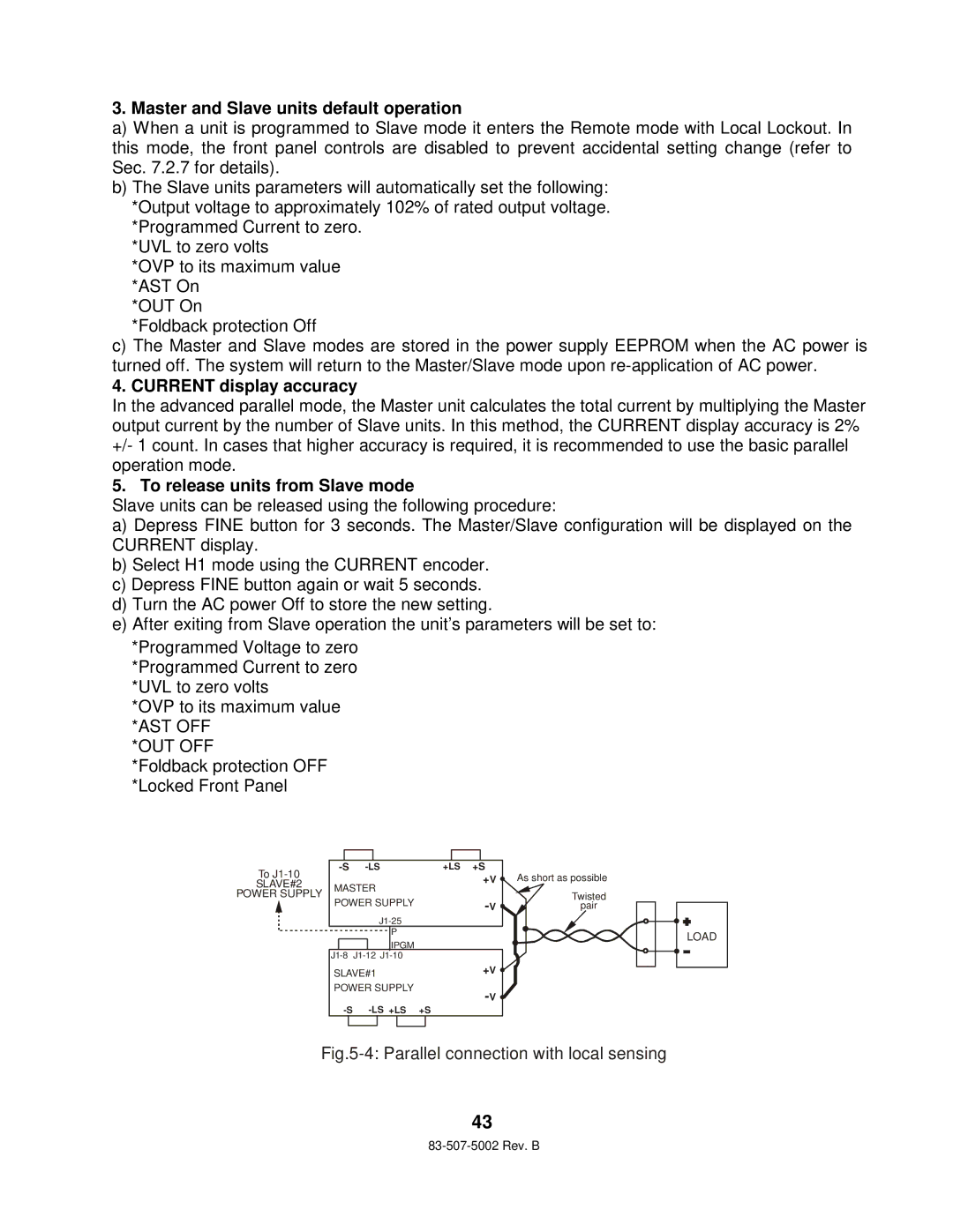
Fig.5-4: Parallel connection with local sensing
43