Table 4-2: Rear panel Connections and Controls (continued)
Number | Item | Description | Section | |
|
|
|
| |
4 | Remote Out | 7.3 | ||
connector | form a serial communication bus. | 7.5 | ||
| ||||
|
|
|
| |
5 | J1 Analog | Connector for remote analog interface. Includes Output Voltage | 4.5 | |
| Remote | and Current programming and monitoring signals, |
| |
| connector | (electrical signal), Enable/Disable control |
| |
|
| ply OK (PS_OK) signal and operation mode (CV/CC) signal. |
| |
6 | SW1 Setup | Nine position | 4.4 | |
| switch | monitoring modes for Output Voltage, Output Current and other |
| |
|
| control functions. |
| |
7 | J2 Remote | Connector for making remote sensing connections to the load for | 3.10 | |
| sense | regulation of the load voltage and compensation of load wire drop. | 3.8.2 | |
| connector |
|
| |
8 | Blank | Blank | Fig. 4.2 | |
| gramming connector for units equipped with Isolated Analog control |
| ||
|
| option. IEEE connector for units equipped with IEEE programming |
| |
|
| option (shown). |
| |
9 | IEEE switch | Two position | Fig. 4.2 | |
|
| mode when IEEE option is installed. |
| |
10 | Ground | M4x0.7, 8mm long | Fig. 4.2 | |
| screw | connection. |
|
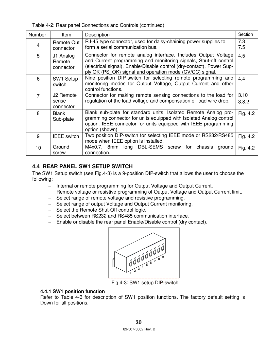
4.4 REAR PANEL SW1 SETUP SWITCH
The SW1 Setup switch (see
−Internal or remote programming for Output Voltage and Output Current.
−Remote voltage or resistive programming of Output Voltage and Output Current limit.
−Select range of remote voltage and resistive programming.
−Select range of output Voltage and Output Current monitoring.
−Select the Remote
−Select between RS232 and RS485 communication interface.
−Enable or disable the rear panel Enable/Disable control (dry contact).
1
2
3
4
5
6 7
8
9
Fig.4-3: SW1 setup DIP-switch
4.4.1 SW1 position function
Refer to Table
30