4.Adjustment resolution can be set to Coarse or Fine adjustment. Press the FINE button to se- lect between the Coarse and Fine resolution. The FINE LED turns On when the resolution is set to FINE.
5.2.3 Automatic Crossover
If the power supply operates in Constant Voltage mode, while the load current is increased to greater than the current limit setting, the power supply will automatically switch to Constant Cur- rent mode. If the load is decreased to less than the current limit setting, the power supply will automatically switch back to Constant Voltage mode.
5.3 OVER VOLTAGE PROTECTION (OVP)
The OVP circuit protects the load in the event of a remote or local programming error or a power supply failure. The protection circuit monitors the voltage at the power supply sense points and thus provides the protection level at the load. Upon detection of an Over Voltage condition, the power supply output will shut down.
5.3.1Setting the OVP level
The OVP can be set when the power supply output is Enabled (On) or Disabled (Off). To set the OVP level, press the OVP/UVL button, so that the CURRENT meter shows “OUP”. The VOLTAGE meter shows the OVP setting level. Rotate the VOLTAGE encoder knob to adjust the OVP level. The display will show “OUP” and the setting value for 5 seconds after the adjustment has been completed, and then will return to its previous state.
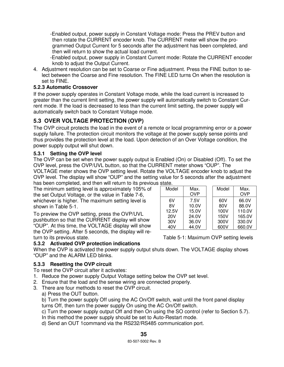
The minimum setting level is approximately 105% of the set Output Voltage, or the value in Table
To preview the OVP setting, press the OVP/UVL pushbutton so that the CURRENT display will show “OUP”. At this time, the VOLTAGE display will show the OVP setting. After 5 seconds, the display will re-
Model | Max. |
| OVP |
6V | 7.5V |
8V | 10.0V |
12.5V | 15.0V |
20V | 24.0V |
30V | 36.0V |
40V | 44.0V |
Model | Max. |
| OVP |
60V | 66.0V |
80V | 88.0V |
100V | 110.0V |
150V | 165.0V |
300V | 330.0V |
600V | 660.0V |
turn to its previous state.
5.3.2Activated OVP protection indications
Table
When the OVP is activated the power supply output shuts down. The VOLTAGE display shows “OUP” and the ALARM LED blinks.
5.3.3Resetting the OVP circuit
To reset the OVP circuit after it activates:
1.Reduce the power supply Output Voltage setting below the OVP set level.
2.Ensure that the load and the sense wiring are connected properly.
3.There are four methods to reset the OVP circuit.
a)Press the OUT button.
b)Turn the power supply Off using the AC On/Off switch, wait until the front panel display turns Off, then turn the power supply On using the AC On/Off switch.
c)Turn the power supply output Off and then On using the SO control (refer to Section 5.7). In this method the power supply should be set to
d)Send an OUT 1command via the RS232/RS485 communication port.
35