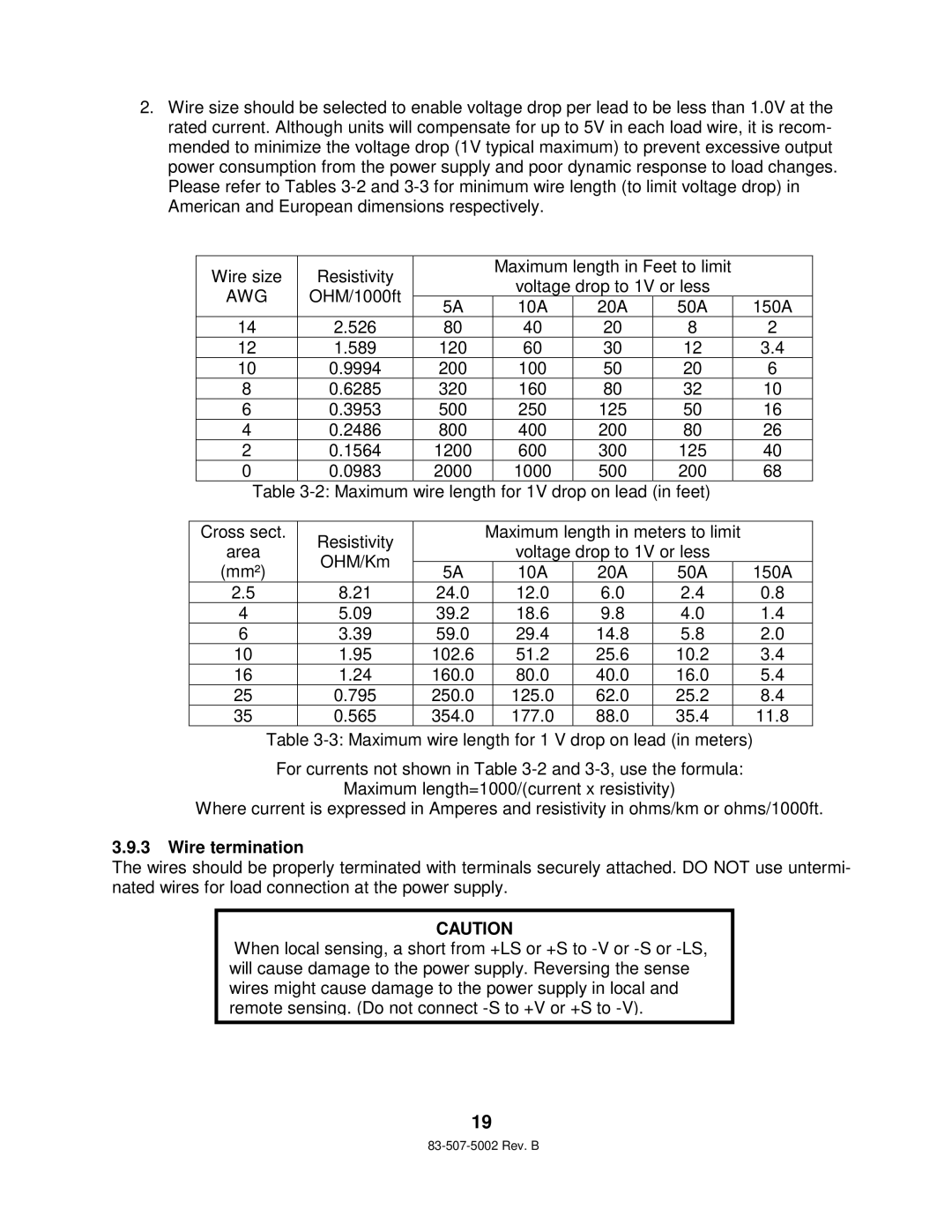
2.Wire size should be selected to enable voltage drop per lead to be less than 1.0V at the rated current. Although units will compensate for up to 5V in each load wire, it is recom- mended to minimize the voltage drop (1V typical maximum) to prevent excessive output power consumption from the power supply and poor dynamic response to load changes. Please refer to Tables
Wire size | Resistivity |
| Maximum length in Feet to limit |
| |||
| voltage drop to 1V or less |
| |||||
AWG | OHM/1000ft |
|
| ||||
5A | 10A | 20A | 50A | 150A | |||
|
| ||||||
14 | 2.526 | 80 | 40 | 20 | 8 | 2 | |
12 | 1.589 | 120 | 60 | 30 | 12 | 3.4 | |
10 | 0.9994 | 200 | 100 | 50 | 20 | 6 | |
8 | 0.6285 | 320 | 160 | 80 | 32 | 10 | |
6 | 0.3953 | 500 | 250 | 125 | 50 | 16 | |
4 | 0.2486 | 800 | 400 | 200 | 80 | 26 | |
2 | 0.1564 | 1200 | 600 | 300 | 125 | 40 | |
0 | 0.0983 | 2000 | 1000 | 500 | 200 | 68 | |
Table
Cross sect. | Resistivity |
| Maximum length in meters to limit |
| ||||
area |
|
| voltage drop to 1V or less |
| ||||
OHM/Km |
|
|
| |||||
(mm²) | 5A |
| 10A | 20A | 50A |
| 150A | |
|
|
| ||||||
2.5 | 8.21 | 24.0 |
| 12.0 | 6.0 | 2.4 |
| 0.8 |
4 | 5.09 | 39.2 |
| 18.6 | 9.8 | 4.0 |
| 1.4 |
6 | 3.39 | 59.0 |
| 29.4 | 14.8 | 5.8 |
| 2.0 |
10 | 1.95 | 102.6 |
| 51.2 | 25.6 | 10.2 |
| 3.4 |
16 | 1.24 | 160.0 |
| 80.0 | 40.0 | 16.0 |
| 5.4 |
25 | 0.795 | 250.0 |
| 125.0 | 62.0 | 25.2 |
| 8.4 |
35 | 0.565 | 354.0 |
| 177.0 | 88.0 | 35.4 |
| 11.8 |
Table
For currents not shown in Table
Maximum length=1000/(current x resistivity)
Where current is expressed in Amperes and resistivity in ohms/km or ohms/1000ft.
3.9.3Wire termination
The wires should be properly terminated with terminals securely attached. DO NOT use untermi- nated wires for load connection at the power supply.
CAUTION
When local sensing, a short from +LS or +S to
19