+V
Power -V
Supply
![]()
![]() +Local sense
+Local sense ![]() +Rem.sense
+Rem.sense ![]()
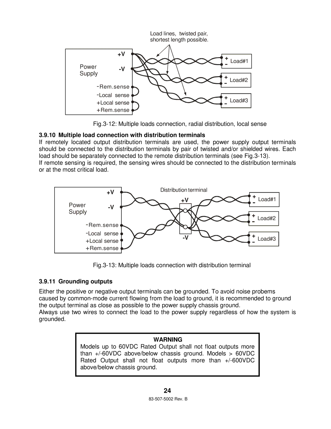
Load lines, twisted pair, shortest length possible.
+ Load#1
+ Load#2
+ Load#3
Fig.3-12: Multiple loads connection, radial distribution, local sense
3.9.10 Multiple load connection with distribution terminals
If remotely located output distribution terminals are used, the power supply output terminals should be connected to the distribution terminals by pair of twisted and/or shielded wires. Each load should be separately connected to the remote distribution terminals (see
If remote sensing is required, the sensing wires should be connected to the distribution terminals or at the most critical load.
+V
Power -V
Supply
![]()
![]() +Local sense
+Local sense ![]() +Rem.sense
+Rem.sense ![]()
Distribution terminal | + Load#1 |
+V | |
| + Load#2 |
+ Load#3 |
Fig.3-13: Multiple loads connection with distribution terminal
3.9.11 Grounding outputs
Either the positive or negative output terminals can be grounded. To avoid noise probems caused by
Always use two wires to connect the load to the power supply regardless of how the system is grounded.
WARNING
Models up to 60VDC Rated Output shall not float outputs more than
24