7.5 CONNECTING POWER SUPPLIES TO RS232 OR RS485 BUS
7.5.1 Single power supply
1.Select the desired interface RS232 or RS485 using rear panel setup switch
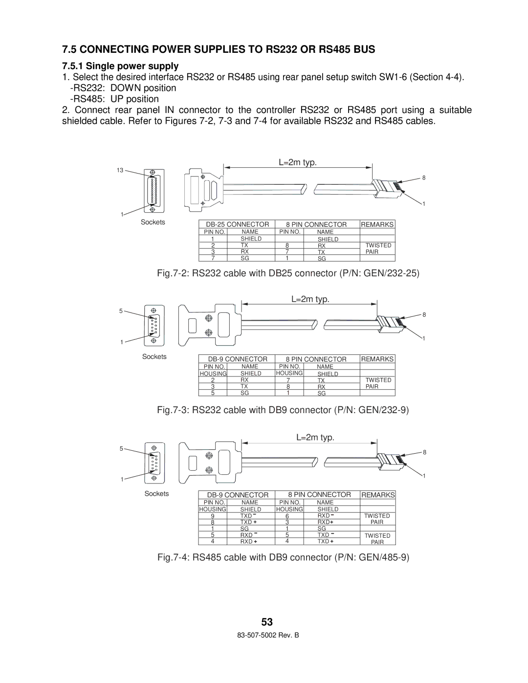
2.Connect rear panel IN connector to the controller RS232 or RS485 port using a suitable shielded cable. Refer to Figures
13
1
5
1
5
1
L=2m typ.
8
![]() 1
1
Sockets |
|
| 8 PIN CONNECTOR | REMARKS | |||
|
|
| PIN NO. | NAME | PIN NO. | NAME |
|
| 1 | SHIELD |
| SHIELD |
| ||
|
|
| 2 | TX | 8 | RX | TWISTED |
|
| 3 | RX | 7 | TX | PAIR | |
| 7 | SG | 1 | SG |
| ||
Fig.7-2: RS232 cable with DB25 connector (P/N: GEN/232-25)
L=2m typ.
![]() 8
8
![]() 1
1
Sockets |
| 8 PIN CONNECTOR |
| REMARKS | ||||
|
| |||||||
|
|
| ||||||
|
| PIN NO. | NAME | PIN NO. | NAME |
|
|
|
|
| HOUSING | SHIELD | HOUSING | SHIELD |
|
|
|
| 2 | RX | 7 | TX |
| TWISTED |
| |
|
| 3 | TX | 8 | RX |
| PAIR | |
| 5 | SG | 1 | SG |
|
|
| |
Fig.7-3: RS232 cable with DB9 connector (P/N: GEN/232-9)
L=2m typ.
![]() 8
8
![]() 1
1
Sockets |
|
|
| 8 PIN CONNECTOR | REMARKS | ||
|
|
| PIN NO. | NAME | PIN NO. | NAME |
|
|
|
| HOUSING | SHIELD | HOUSING | SHIELD |
|
| 9 | TXD - | 6 | RXD- | TWISTED | ||
|
| 8 | TXD + | 3 | RXD+ | PAIR | |
|
| 1 | SG | 1 | SG |
| |
|
| 5 | RXD - | 5 | TXD - | TWISTED | |
|
| 4 | RXD + | 4 | TXD + | PAIR | |
Fig.7-4: RS485 cable with DB9 connector (P/N: GEN/485-9)
53