CHAPTER 4 FRONT AND REAR PANEL CONTROLS AND CONNECTORS
4.1 INTRODUCTION
The GenesysTM Power Supply series has a full set of controls, indicators and connectors that al- low the user to easily setup and operate the unit. Before starting to operate the unit, please read the following Sections for explanation of the functions of the controls and connectors terminals.
4.2 FRONT PANEL CONTROLS AND INDICATORS
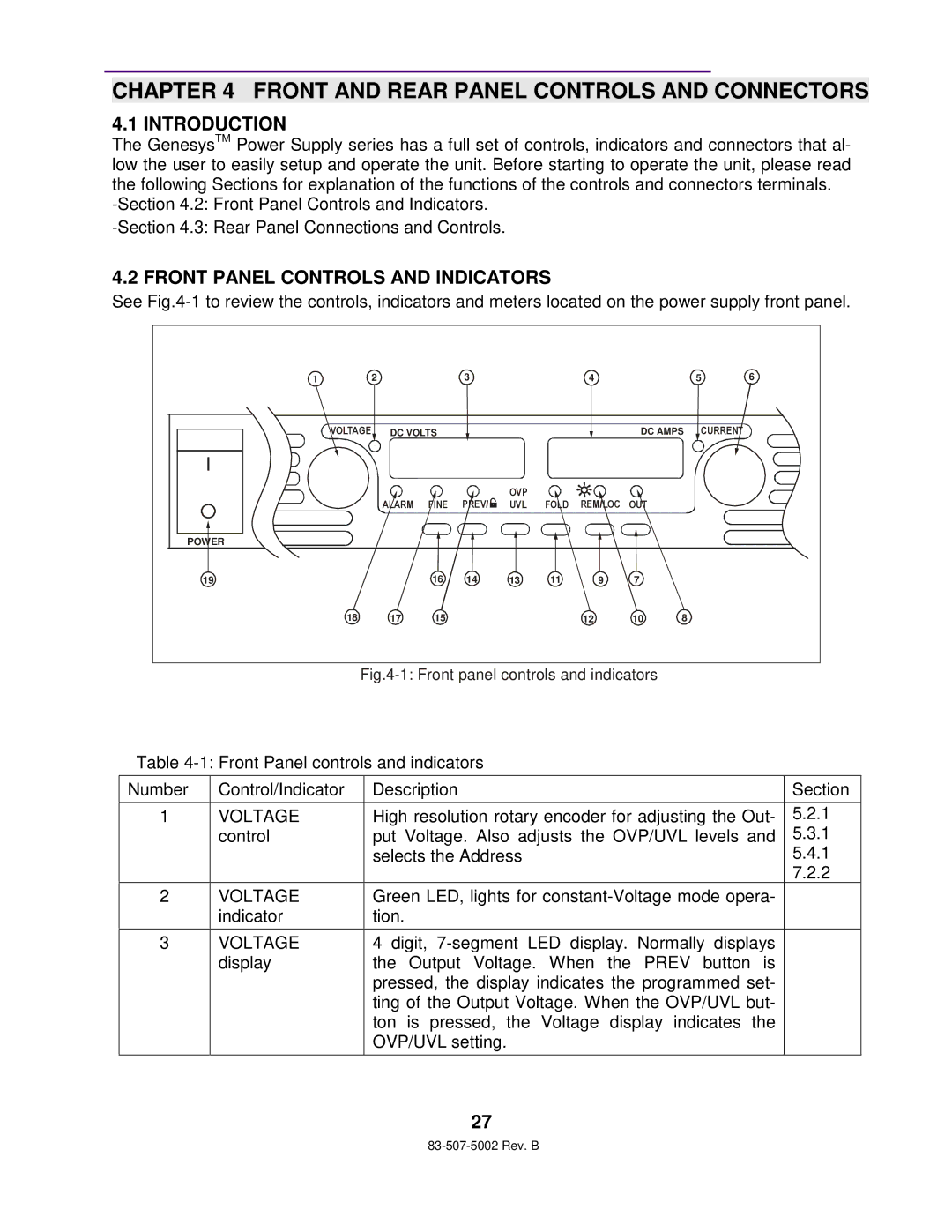
See
1 | 2 |
|
| 3 |
|
| 4 |
|
| 5 | 6 |
| VOLTAGE | DC VOLTS |
|
|
|
| DC AMPS | CURRENT |
| ||
|
|
|
|
| OVP |
|
|
|
|
|
|
|
| ALARM | FINE | PREV/ | UVL |
| REM/LOC | OUT |
|
|
|
POWER |
|
|
|
|
|
|
|
|
|
|
|
19 |
|
| 16 | 14 | 13 | 11 | 9 | 7 |
|
|
|
| 18 | 17 | 15 |
|
|
| 12 | 10 | 8 |
|
|
Fig.4-1: Front panel controls and indicators
Table
Number | Control/Indicator | Description | Section |
|
|
|
|
1 | VOLTAGE | High resolution rotary encoder for adjusting the Out- | 5.2.1 |
| control | put Voltage. Also adjusts the OVP/UVL levels and | 5.3.1 |
|
| selects the Address | 5.4.1 |
|
|
| 7.2.2 |
2 | VOLTAGE | Green LED, lights for |
|
| indicator | tion. |
|
|
|
|
|
3 | VOLTAGE | 4 digit, |
|
| display | the Output Voltage. When the PREV button is |
|
|
| pressed, the display indicates the programmed set- |
|
|
| ting of the Output Voltage. When the OVP/UVL but- |
|
|
| ton is pressed, the Voltage display indicates the |
|
|
| OVP/UVL setting. |
|
|
|
|
|
27