During operation, the Slave units operate as a controlled current source following the Master Output Current. It is recommended that the power system be designed so that each unit supplies up to 95% of its current rating because of the imbalance which may be caused by cabling and connection voltage drop.
3.Setting Over Voltage protection
The Master unit OVP setting should be programmed to the desired OVP level. The OVP set- ting of the slave units should be programmed to a higher value than the Master OVP. When the Master unit shuts down, it programs the Slave unit to zero Output Voltage. If a Slave unit shuts down (when its OVP is set lower than the Master Output Voltage), only that Slave unit would shut down, and the remaining Slave units would supply all the load current.
4.Setting Foldback protection
Foldback protection, is desired, may only be used with the Master unit. When the Master unit shuts down, it programs the Slave units to zero Output Voltage.
5.Connection to the load
In parallel operation, power supplies can be connected in local or remote sensing. Refer to Fig.
5.15.2 Advanced parallel operation
In this method, multiple supplies can be configured to parallel operation as a single power supply. The total load current and output voltage are displayed by the Master unit and can be readback from the Master unit. The Slave units display only their operating status (On, Off or Fault condi- tion).
Refer to the following procedure to configure multiple supplies for Advanced parallel operation.
1.Advanced parallel configuration
∙SW1 position 2 - Down in the Master Supply and up in all Slave Supplies.
∙Connect a short between
∙Connect
∙Connect
∙Connect
∙Connect
∙Connect
∙Connect
∙Select Local or Remote sense - Ref. Figures
2.Setting the units as Master or Slave
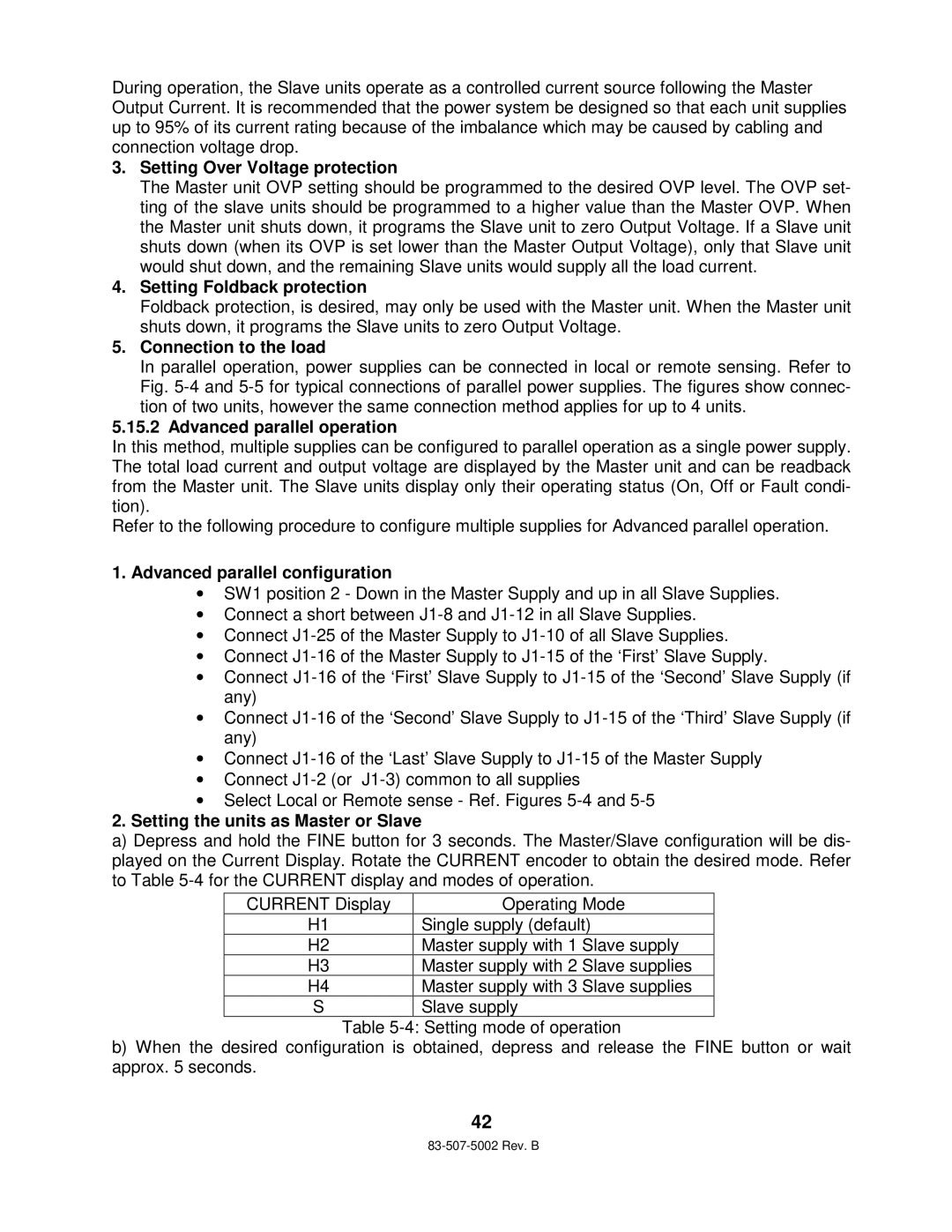
a)Depress and hold the FINE button for 3 seconds. The Master/Slave configuration will be dis- played on the Current Display. Rotate the CURRENT encoder to obtain the desired mode. Refer to Table
CURRENT Display | Operating Mode | |
H1 | Single supply (default) | |
H2 | Master supply with 1 | Slave supply |
H3 | Master supply with 2 | Slave supplies |
H4 | Master supply with 3 | Slave supplies |
S | Slave supply |
|
Table
b)When the desired configuration is obtained, depress and release the FINE button or wait approx. 5 seconds.
42