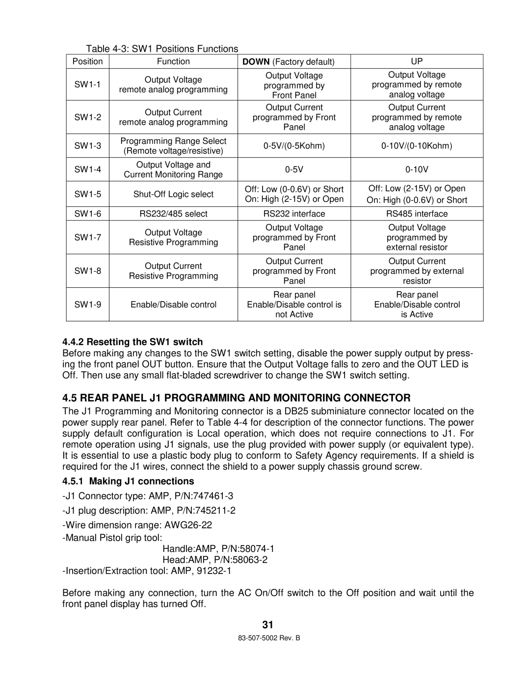
Table 4-3: SW1 Positions Functions
Position | Function | DOWN (Factory default) | UP | |
|
|
|
| |
| Output Voltage | Output Voltage | Output Voltage | |
programmed by | programmed by remote | |||
remote analog programming | ||||
| Front Panel | analog voltage | ||
|
| |||
| Output Current | Output Current | Output Current | |
programmed by Front | programmed by remote | |||
remote analog programming | ||||
| Panel | analog voltage | ||
|
| |||
|
|
|
| |
Programming Range Select | ||||
(Remote voltage/resistive) | ||||
|
|
| ||
|
|
|
| |
Output Voltage and | ||||
Current Monitoring Range | ||||
|
|
| ||
|
|
|
| |
Off: Low | Off: Low | |||
On: High | On: High | |||
|
| |||
|
|
|
| |
RS232/485 select | RS232 interface | RS485 interface | ||
|
|
|
| |
| Output Voltage | Output Voltage | Output Voltage | |
programmed by Front | programmed by | |||
Resistive Programming | ||||
| Panel | external resistor | ||
|
| |||
|
|
|
| |
| Output Current | Output Current | Output Current | |
programmed by Front | programmed by external | |||
Resistive Programming | ||||
| Panel | resistor | ||
|
| |||
|
|
|
| |
|
| Rear panel | Rear panel | |
Enable/Disable control | Enable/Disable control is | Enable/Disable control | ||
|
| not Active | is Active | |
|
|
|
|
4.4.2 Resetting the SW1 switch
Before making any changes to the SW1 switch setting, disable the power supply output by press- ing the front panel OUT button. Ensure that the Output Voltage falls to zero and the OUT LED is Off. Then use any small
4.5 REAR PANEL J1 PROGRAMMING AND MONITORING CONNECTOR
The J1 Programming and Monitoring connector is a DB25 subminiature connector located on the power supply rear panel. Refer to Table
4.5.1 Making J1 connections
Handle:AMP,
Head:AMP,
Before making any connection, turn the AC On/Off switch to the Off position and wait until the front panel display has turned Off.
31