8.3 ISOLATED PROGRAMMING & MONITORING CONNECTOR
Refer to Table
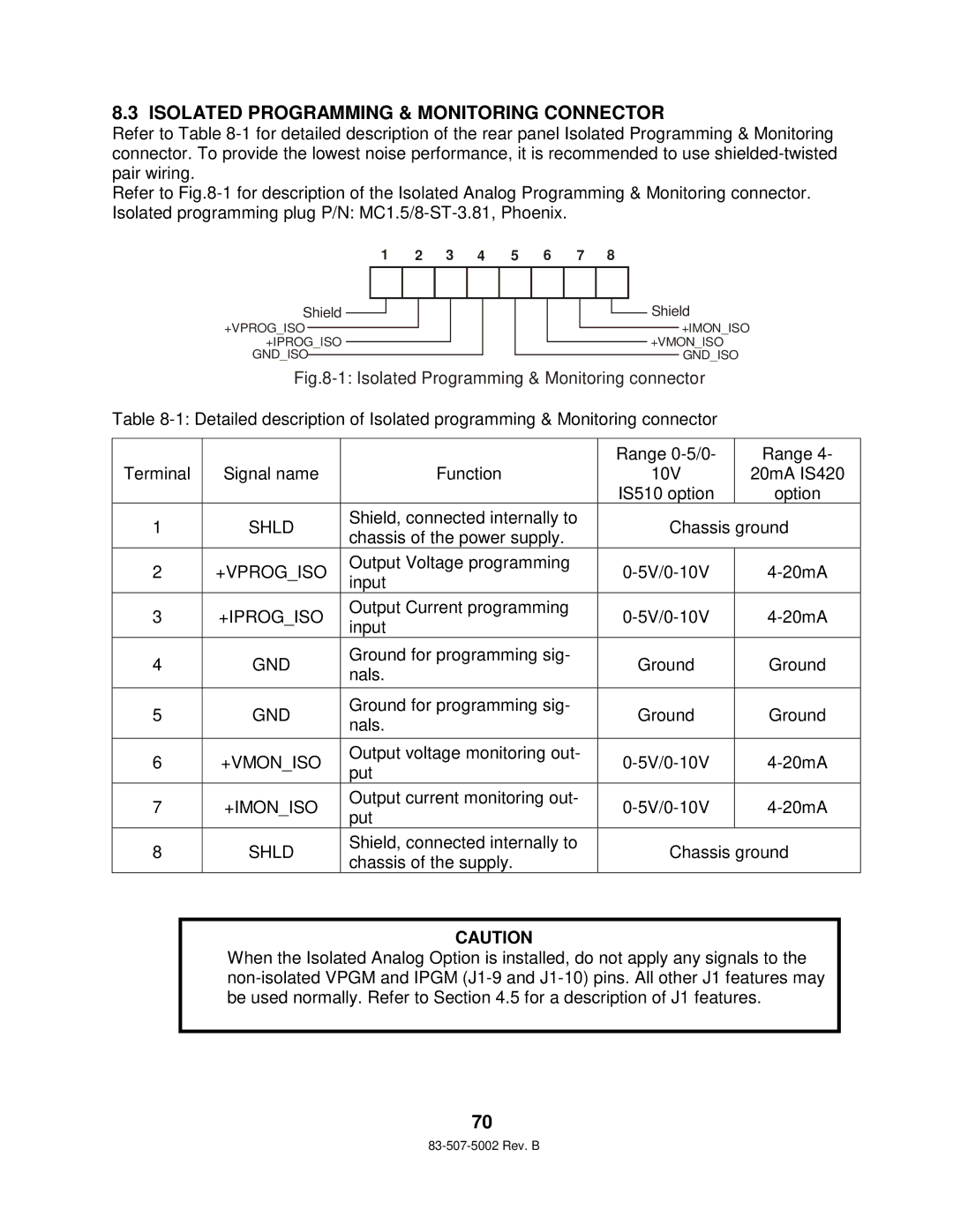
Refer to
1 | 2 | 3 | 4 | 5 | 6 | 7 | 8 |
Shield
+VPROG_ISO +IPROG_ISO
GND_ISO
![]() Shield
Shield
+IMON_ISO
+VMON_ISO GND_ISO
Fig.8-1: Isolated Programming & Monitoring connector
Table
|
|
| Range | Range 4- | |
Terminal | Signal name | Function | 10V | 20mA IS420 | |
|
|
| IS510 option | option | |
1 | SHLD | Shield, connected internally to | Chassis ground | ||
chassis of the power supply. | |||||
|
|
|
| ||
2 | +VPROG_ISO | Output Voltage programming | |||
input | |||||
|
|
|
| ||
3 | +IPROG_ISO | Output Current programming | |||
input | |||||
|
|
|
| ||
4 | GND | Ground for programming sig- | Ground | Ground | |
nals. | |||||
|
|
|
| ||
|
|
|
|
| |
5 | GND | Ground for programming sig- | Ground | Ground | |
nals. | |||||
|
|
|
| ||
|
|
|
|
| |
6 | +VMON_ISO | Output voltage monitoring out- | |||
put | |||||
|
|
|
| ||
7 | +IMON_ISO | Output current monitoring out- | |||
put | |||||
|
|
|
| ||
8 | SHLD | Shield, connected internally to | Chassis ground | ||
chassis of the supply. | |||||
|
|
|
| ||
CAUTION
When the Isolated Analog Option is installed, do not apply any signals to the
70