6.4REMOTE VOLTAGE PROGRAMMING OF OUTPUT VOLTAGE AND OUTPUT CURRENT LIMIT
CAUTION
To maintain the power supply isolation and to prevent ground loops, use an isolated programming source when operating the power supply via remote analog programming at the J1 connector.
Perform the following procedure to set the power supply to Remote Voltage programming:
1.Turn the power supply AC On/Off switch to Off.
2.Set setup switch SW1, positions 1 and 2 to their UP position.
3.Set SW1, position 3 to select the programming voltage range according to Table
4.Ensure that SW1, positions 7 and 8 are at their DOWN (default) position.
5.Connect a wire jumper between
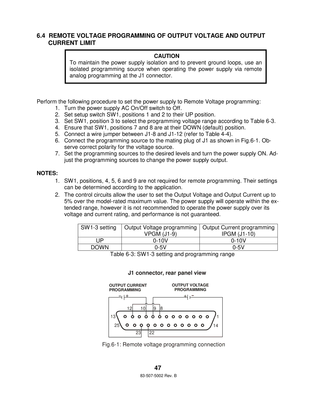
6.Connect the programming source to the mating plug of J1 as shown in
7.Set the programming sources to the desired levels and turn the power supply ON. Ad- just the programming sources to change the power supply output.
NOTES:
1.SW1, positions, 4, 5, 6 and 9 are not required for remote programming. Their settings can be determined according to the application.
2.The control circuits allow the user to set the Output Voltage and Output Current up to 5% over the
Output Voltage programming | Output Current programming | |
| VPGM | IPGM |
UP | ||
DOWN |
Table
J1 connector, rear panel view
OUTPUT CURRENT PROGRAMMING
+
OUTPUT VOLTAGE |
PROGRAMMING |
+ |
13![]()
![]()
12 | 10 |
|
|
|
| 8 |
9 | ||
|
| 1 |
|
| |
25![]()
![]()
![]()
23
14 |
22 |
Fig.6-1: Remote voltage programming connection
47