The 80V to 600V models have a four terminal wire clamp output connector. The two left terminals are the positive outputs and the two right terminals are the negative outputs. The connector re- quirements are as follows:
1.Wires: AWG18 to AWG10.
2.Tightening torque:
Follow the instructions below for connection of the load wires to the power supply:
1.Strip approx. 10mm (0.39 inches) at the end of each of the wires.
2.Loosen the connector terminal screws.
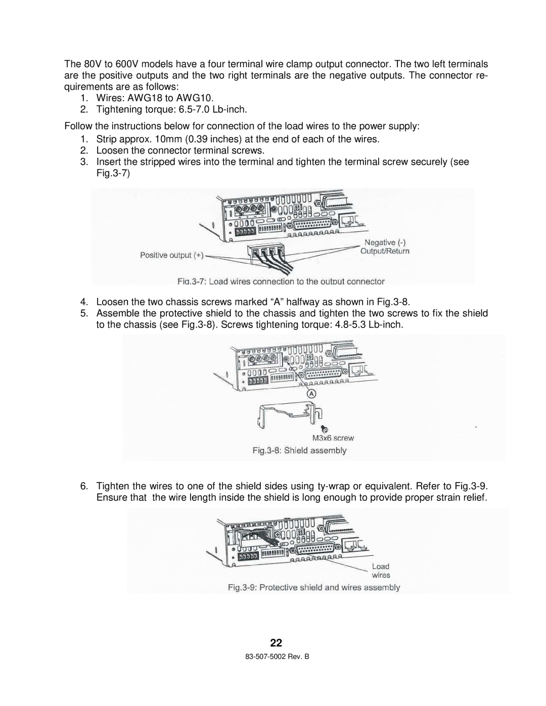
3.Insert the stripped wires into the terminal and tighten the terminal screw securely (see
4.Loosen the two chassis screws marked “A” halfway as shown in
5.Assemble the protective shield to the chassis and tighten the two screws to fix the shield to the chassis (see
6.Tighten the wires to one of the shield sides using
22