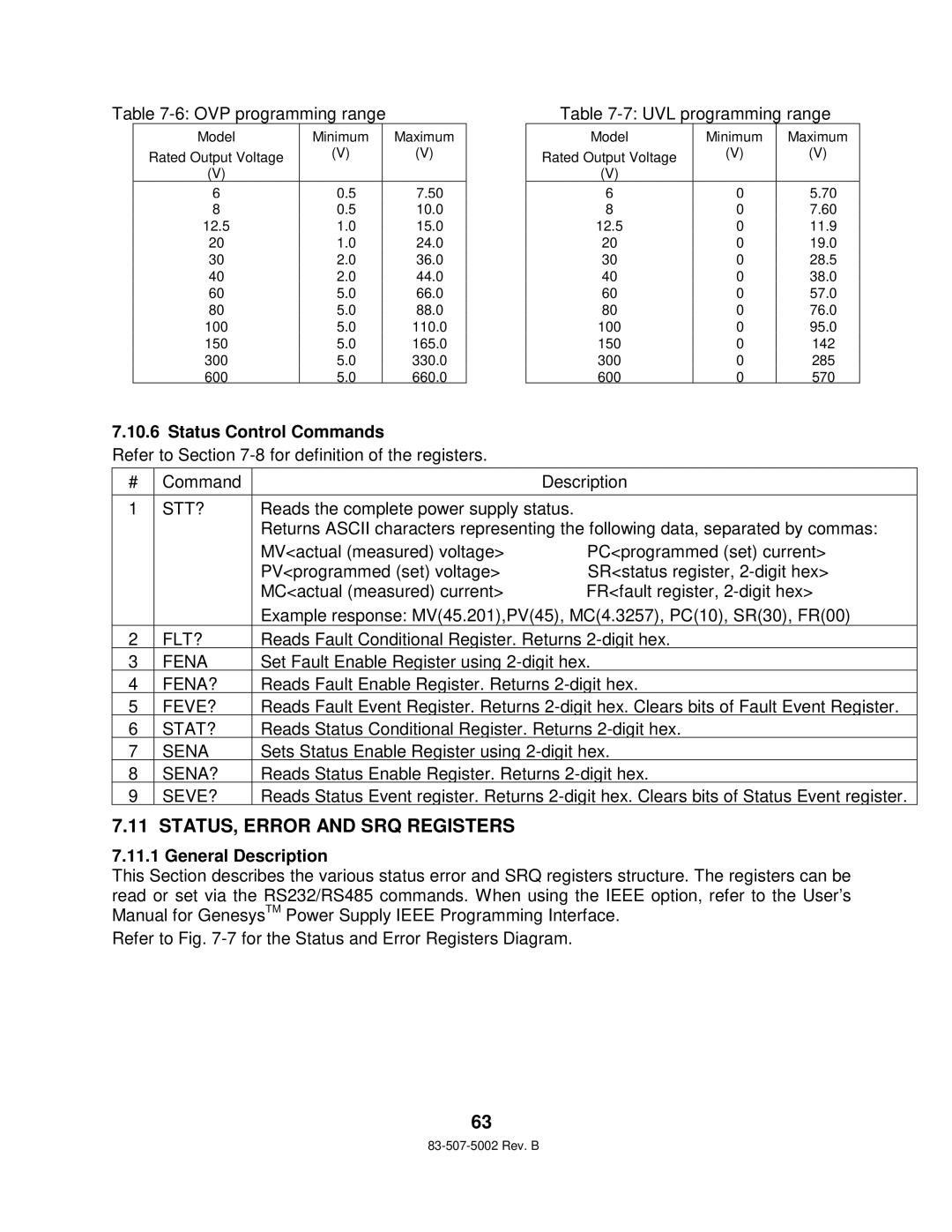
Table 7-6: OVP programming range
Model | Minimum | Maximum |
Rated Output Voltage | (V) | (V) |
|
| |
(V) |
|
|
6 | 0.5 | 7.50 |
8 | 0.5 | 10.0 |
12.5 | 1.0 | 15.0 |
20 | 1.0 | 24.0 |
30 | 2.0 | 36.0 |
40 | 2.0 | 44.0 |
60 | 5.0 | 66.0 |
80 | 5.0 | 88.0 |
100 | 5.0 | 110.0 |
150 | 5.0 | 165.0 |
300 | 5.0 | 330.0 |
600 | 5.0 | 660.0 |
Table 7-7: UVL programming range
Model | Minimum | Maximum |
Rated Output Voltage | (V) | (V) |
|
| |
(V) |
|
|
6 | 0 | 5.70 |
8 | 0 | 7.60 |
12.5 | 0 | 11.9 |
20 | 0 | 19.0 |
30 | 0 | 28.5 |
40 | 0 | 38.0 |
60 | 0 | 57.0 |
80 | 0 | 76.0 |
100 | 0 | 95.0 |
150 | 0 | 142 |
300 | 0 | 285 |
600 | 0 | 570 |
7.10.6 Status Control Commands
Refer to Section
# | Command |
| Description |
|
|
| |
1 | STT? | Reads the complete power supply status. | |
|
| Returns ASCII characters representing the following data, separated by commas: | |
|
| MV<actual (measured) voltage> | PC<programmed (set) current> |
|
| PV<programmed (set) voltage> | SR<status register, |
|
| MC<actual (measured) current> | FR<fault register, |
|
| Example response: MV(45.201),PV(45), MC(4.3257), PC(10), SR(30), FR(00) | |
2 | FLT? | Reads Fault Conditional Register. Returns | |
3 | FENA | Set Fault Enable Register using | |
4 | FENA? | Reads Fault Enable Register. Returns | |
5 | FEVE? | Reads Fault Event Register. Returns | |
6 | STAT? | Reads Status Conditional Register. Returns | |
7 | SENA | Sets Status Enable Register using | |
8 | SENA? | Reads Status Enable Register. Returns | |
9 | SEVE? | Reads Status Event register. Returns | |
7.11 STATUS, ERROR AND SRQ REGISTERS
7.11.1 General Description
This Section describes the various status error and SRQ registers structure. The registers can be read or set via the RS232/RS485 commands. When using the IEEE option, refer to the User’s Manual for GenesysTM Power Supply IEEE Programming Interface.
Refer to Fig.
63