Table
Number | Control/Indicator | Description | Section |
|
|
|
|
15 | PREV indicator | Green LED, lights when PREV button is pressed |
|
|
|
|
|
16 | FINE button | Voltage and Current Fine/Coarse adjustment control. Op- |
|
|
| erates as a toggle switch. In Fine mode, the VOLTAGE |
|
|
| and CURRENT encoders operate with high resolution and |
|
|
| in Coarse mode with lower resolution (approx. 6 turns). |
|
|
| Auxiliary function: Set units as Master or Slave in Ad- | 5.15.2 |
|
| vanced parallel operation. |
|
17 | FINE indicator | Green LED, lights when the unit is in Fine mode. |
|
|
|
|
|
18 | ALARM indicator | Red LED, blinks in case of fault detection. OVP, OTP |
|
|
| Foldback, Enable and AC fail detection will cause the |
|
|
| ALARM LED to blink. |
|
19 | AC Power switch | AC On/Off control. |
|
|
|
|
|
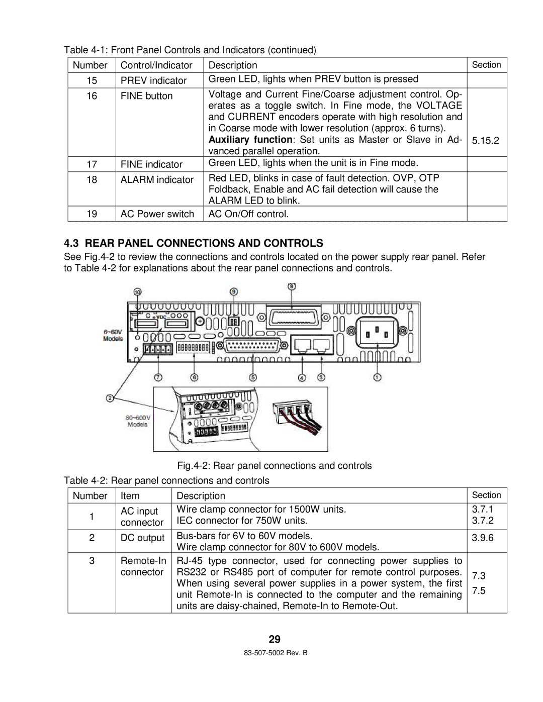
4.3 REAR PANEL CONNECTIONS AND CONTROLS
See
Fig.4-2: Rear panel connections and controls
Table
Number | Item | Description | Section | |
|
|
|
| |
1 | AC input | Wire clamp connector for 1500W units. | 3.7.1 | |
connector | IEC connector for 750W units. | 3.7.2 | ||
| ||||
|
|
|
| |
2 | DC output | 3.9.6 | ||
|
| Wire clamp connector for 80V to 600V models. |
| |
3 |
| |||
| connector | RS232 or RS485 port of computer for remote control purposes. | 7.3 | |
|
| When using several power supplies in a power system, the first | ||
|
| 7.5 | ||
|
| unit | ||
|
|
| ||
|
| units are |
| |
|
|
|
|
29