www.ti.com | Overview |
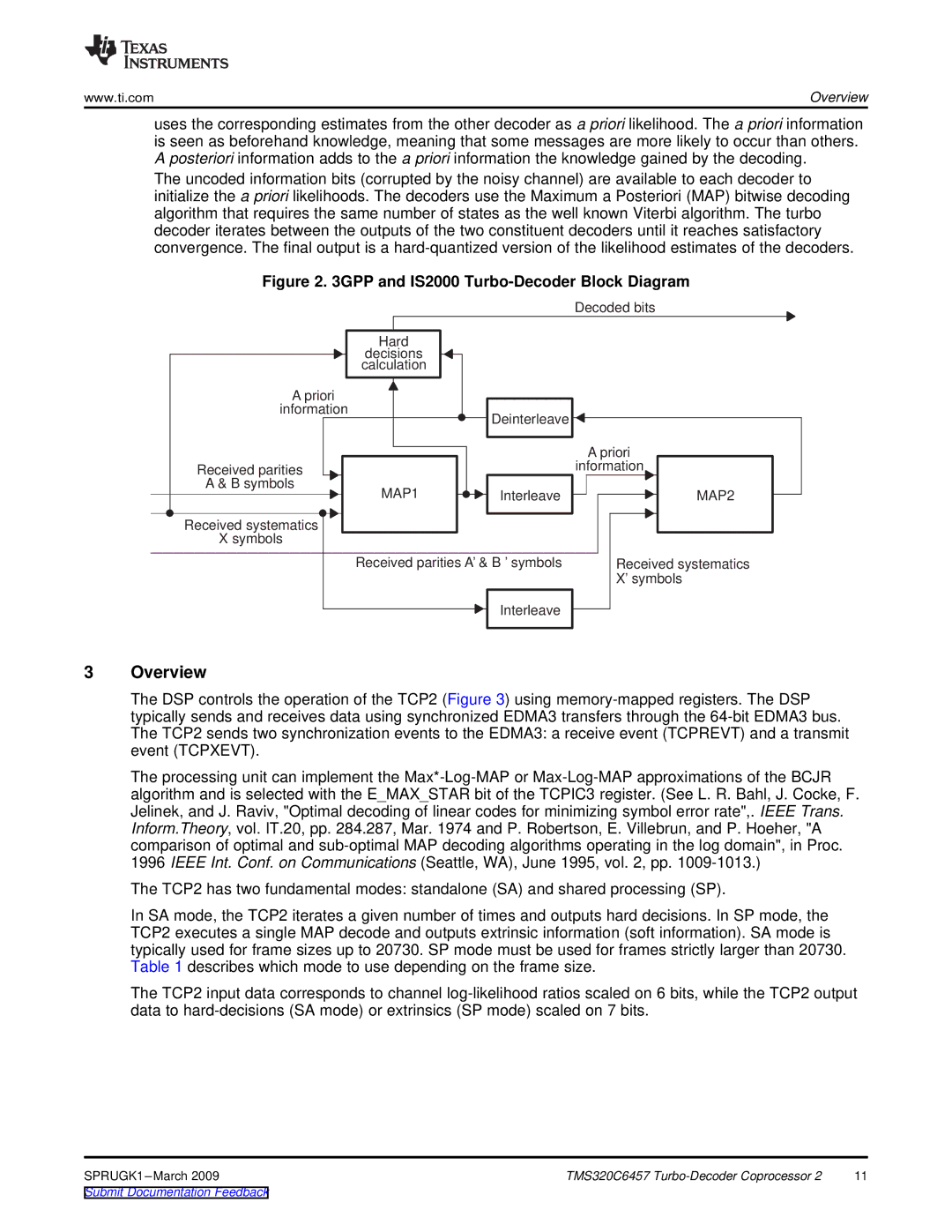
uses the corresponding estimates from the other decoder as a priori likelihood. The a priori information is seen as beforehand knowledge, meaning that some messages are more likely to occur than others. A posteriori information adds to the a priori information the knowledge gained by the decoding.
The uncoded information bits (corrupted by the noisy channel) are available to each decoder to initialize the a priori likelihoods. The decoders use the Maximum a Posteriori (MAP) bitwise decoding algorithm that requires the same number of states as the well known Viterbi algorithm. The turbo decoder iterates between the outputs of the two constituent decoders until it reaches satisfactory convergence. The final output is a
Figure 2. 3GPP and IS2000 Turbo-Decoder Block Diagram
Decoded bits
| Hard |
|
|
| decisions |
|
|
| calculation |
|
|
| A priori |
|
|
| information | Deinterleave |
|
|
|
| |
|
|
| A priori |
| Received parities |
| information |
| A & B symbols | Interleave | MAP2 |
| MAP1 | ||
| Received systematics |
|
|
| X symbols |
|
|
| Received parities A’ & B ’ symbols | Received systematics | |
|
|
| X’ symbols |
|
| Interleave |
|
3 | Overview |
|
|
The DSP controls the operation of the TCP2 (Figure 3) using
The processing unit can implement the
The TCP2 has two fundamental modes: standalone (SA) and shared processing (SP).
In SA mode, the TCP2 iterates a given number of times and outputs hard decisions. In SP mode, the TCP2 executes a single MAP decode and outputs extrinsic information (soft information). SA mode is typically used for frame sizes up to 20730. SP mode must be used for frames strictly larger than 20730. Table 1 describes which mode to use depending on the frame size.
The TCP2 input data corresponds to channel
TMS320C6457 | 11 |
