Registers | www.ti.com |
6.2TCP2 Input Configuration Register 0 (TCPIC0)
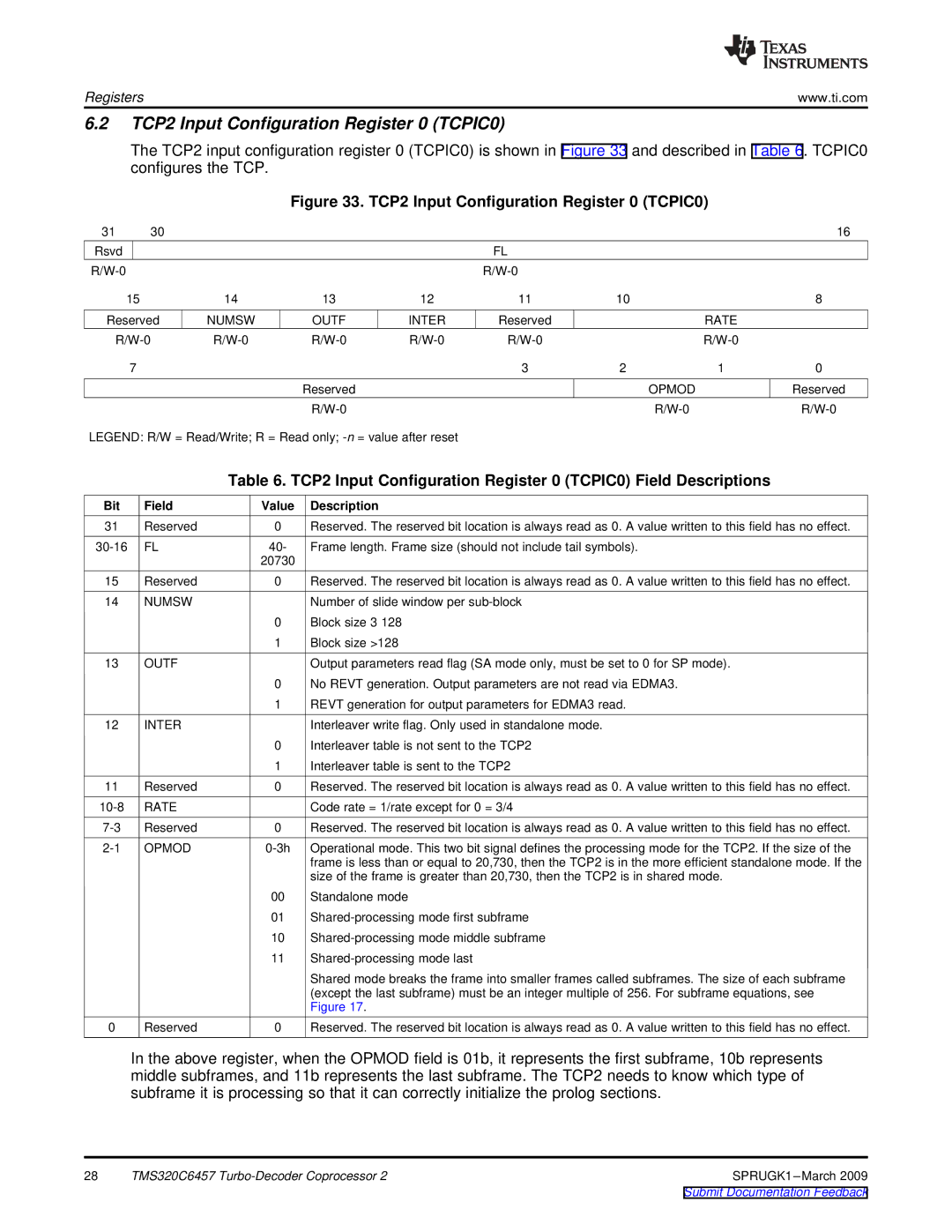
The TCP2 input configuration register 0 (TCPIC0) is shown in Figure 33 and described in Table 6. TCPIC0 configures the TCP.
Figure 33. TCP2 Input Configuration Register 0 (TCPIC0)
31 | 30 |
|
|
|
|
|
| 16 |
Rsvd |
|
|
|
| FL |
|
|
|
|
|
|
|
|
|
| ||
15 |
| 14 | 13 | 12 | 11 | 10 |
| 8 |
Reserved | NUMSW | OUTF | INTER | Reserved |
| RATE |
| |
|
|
| ||||||
7 |
|
|
|
| 3 | 2 | 1 | 0 |
|
|
| Reserved |
|
| OPMOD |
| Reserved |
|
|
|
|
|
| |||
LEGEND: R/W = Read/Write; R = Read only;
Table 6. TCP2 Input Configuration Register 0 (TCPIC0) Field Descriptions
Bit | Field | Value | Description |
31 | Reserved | 0 | Reserved. The reserved bit location is always read as 0. A value written to this field has no effect. |
FL | 40- | Frame length. Frame size (should not include tail symbols). | |
|
| 20730 |
|
15 | Reserved | 0 | Reserved. The reserved bit location is always read as 0. A value written to this field has no effect. |
14 | NUMSW |
| Number of slide window per |
|
| 0 | Block size 3 128 |
|
| 1 | Block size >128 |
13 | OUTF |
| Output parameters read flag (SA mode only, must be set to 0 for SP mode). |
|
| 0 | No REVT generation. Output parameters are not read via EDMA3. |
|
| 1 | REVT generation for output parameters for EDMA3 read. |
12 | INTER |
| Interleaver write flag. Only used in standalone mode. |
|
| 0 | Interleaver table is not sent to the TCP2 |
|
| 1 | Interleaver table is sent to the TCP2 |
11 | Reserved | 0 | Reserved. The reserved bit location is always read as 0. A value written to this field has no effect. |
RATE |
| Code rate = 1/rate except for 0 = 3/4 | |
Reserved | 0 | Reserved. The reserved bit location is always read as 0. A value written to this field has no effect. | |
OPMOD | Operational mode. This two bit signal defines the processing mode for the TCP2. If the size of the | ||
|
|
| frame is less than or equal to 20,730, then the TCP2 is in the more efficient standalone mode. If the |
|
|
| size of the frame is greater than 20,730, then the TCP2 is in shared mode. |
|
| 00 | Standalone mode |
|
| 01 | |
|
| 10 | |
|
| 11 | |
|
|
| Shared mode breaks the frame into smaller frames called subframes. The size of each subframe |
|
|
| (except the last subframe) must be an integer multiple of 256. For subframe equations, see |
|
|
| Figure 17. |
0 | Reserved | 0 | Reserved. The reserved bit location is always read as 0. A value written to this field has no effect. |
In the above register, when the OPMOD field is 01b, it represents the first subframe, 10b represents middle subframes, and 11b represents the last subframe. The TCP2 needs to know which type of subframe it is processing so that it can correctly initialize the prolog sections.
28 | TMS320C6457 |