www.ti.com |
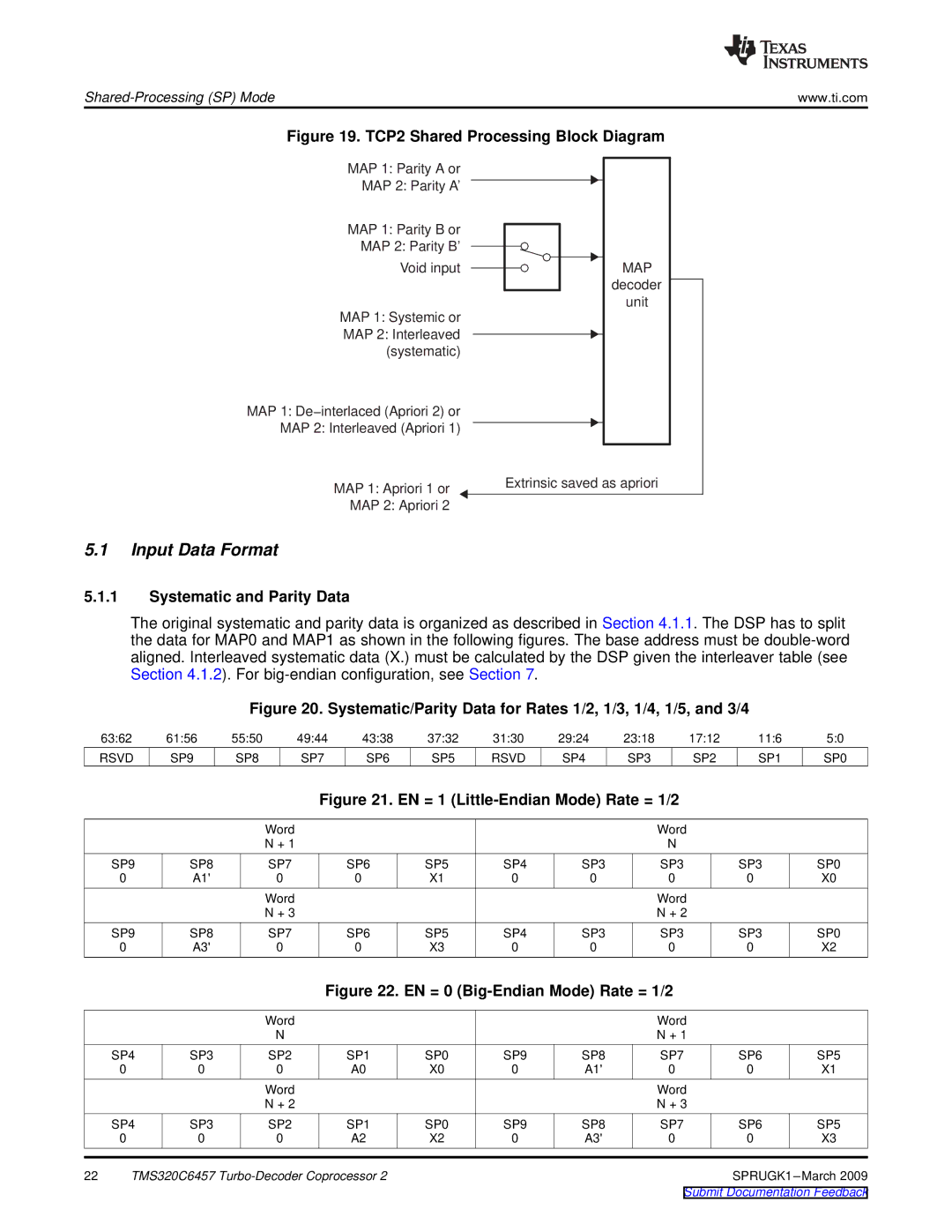
Figure 19. TCP2 Shared Processing Block Diagram
MAP 1: Parity A or
MAP 2: Parity A'
MAP 1: Parity B or
MAP 2: Parity B'
Void input
MAP 1: Systemic or
MAP 2: Interleaved (systematic)
MAP 1: De−interlaced (Apriori 2) or MAP 2: Interleaved (Apriori 1)
MAP decoder unit
MAP 1: Apriori 1 or | Extrinsic saved as apriori |
MAP 2: Apriori 2 |
|
5.1Input Data Format
5.1.1Systematic and Parity Data
The original systematic and parity data is organized as described in Section 4.1.1. The DSP has to split the data for MAP0 and MAP1 as shown in the following figures. The base address must be
Figure 20. Systematic/Parity Data for Rates 1/2, 1/3, 1/4, 1/5, and 3/4
63:62 | 61:56 | 55:50 | 49:44 | 43:38 | 37:32 | 31:30 | 29:24 | 23:18 | 17:12 | 11:6 | 5:0 |
RSVD | SP9 | SP8 | SP7 | SP6 | SP5 | RSVD | SP4 | SP3 | SP2 | SP1 | SP0 |
Figure 21. EN = 1 (Little-Endian Mode) Rate = 1/2
|
| Word |
|
|
|
| Word |
|
|
|
| N + 1 |
|
|
|
| N |
|
|
SP9 | SP8 | SP7 | SP6 | SP5 | SP4 | SP3 | SP3 | SP3 | SP0 |
0 | A1' | 0 | 0 | X1 | 0 | 0 | 0 | 0 | X0 |
|
| Word |
|
|
|
| Word |
|
|
|
| N + 3 |
|
|
|
| N + 2 |
|
|
SP9 | SP8 | SP7 | SP6 | SP5 | SP4 | SP3 | SP3 | SP3 | SP0 |
0 | A3' | 0 | 0 | X3 | 0 | 0 | 0 | 0 | X2 |
Figure 22. EN = 0 (Big-Endian Mode) Rate = 1/2
|
|
| Word |
|
|
|
| Word |
|
|
|
|
| N |
|
|
|
| N + 1 |
|
|
| SP4 | SP3 | SP2 | SP1 | SP0 | SP9 | SP8 | SP7 | SP6 | SP5 |
| 0 | 0 | 0 | A0 | X0 | 0 | A1' | 0 | 0 | X1 |
|
|
| Word |
|
|
|
| Word |
|
|
|
|
| N + 2 |
|
|
|
| N + 3 |
|
|
| SP4 | SP3 | SP2 | SP1 | SP0 | SP9 | SP8 | SP7 | SP6 | SP5 |
| 0 | 0 | 0 | A2 | X2 | 0 | A3' | 0 | 0 | X3 |
22 | TMS320C6457 |
|
|
|
| |||||