Operator’s Manual for Facsimile and Copy Functions
Useful Office Functions
Precautions See pages
Operators Manual Outline
Symbols/Icons
Input text with Qwerty keyboard
Mode Setting
Table of Contents
Precautions
Control Panel
Sending Documents
Timer Controlled Communications
PIN Code Access
Receiving Documents
Creative Features
Edit File Mode
Access Code
Other Features
User Parameters For Facsimile 108
Adjusting the Volume and Dialing Method Tone or Pulse
Programming Auto Dialer
Fax Parameters 110
152
Specifications 142 Glossary 146 ITU-T Image No 151
Replacing the Battery
Verification Stamp
Disclaimer Notice
Installation and Relocation Cautions
Precautions
For Your Safety
Power and Ground Connection Cautions
Operating Safeguards
Others
Consumable Safeguards
Illegal Copies
Installation
Supplies
Ambient conditions
Handling
Procedures
Ventilation
Input DEPT. Code
Laser Safety
Laser Safety
Important Safety Instructions
Toshiba America Business SOLUTIONS, INC
FCC Notice for Users in USA
Toshiba
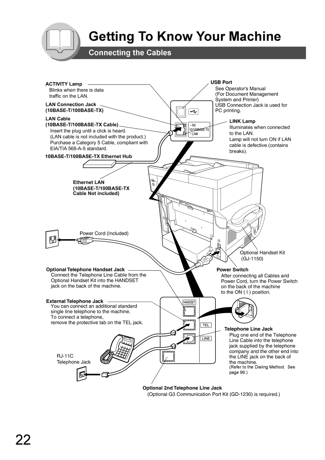
Getting To Know Your Machine
Avis
Activity Lamp
Connecting the Cables
Link Lamp
Directory Search and Quick Name Search
Manual Number Dialing Up to 50 Stations
Operation Chart
One-Touch/ABBR. Dialing see Note
3d Directory Search Dialing
Halftone 600 dpi
Transmission Settings
Contrast
Dialing No. Indication Sample
To Stop the Transmission
Using the ADF
Making Copies
Print COMM. JOURNAL? 1YES 2NO
Before Pressing the Start Key Rear Cover Making Copies Catch
Adding Paper Paper Trays Tray-1 and Tray-2
Adding Paper Sheet Bypass
For Tray-1
Problem Solving
Paper Weight
For Tray-2
Toner is Nearly Empty
Problem Solving ƒ Replacing Toner Cartridge and Drum Unit
Toner is Low
Toner is Empty
NEW Toner REPLACED? 1YES 2NO Toner REPLACEMENT? 1YES 2NO
J01, J02, J43, J44, J80
ƒ Removing a Misfed Paper ADF J71, J72, J74, J75, J92, J93
J43, J44, J82, J83
Rear Side
Misfed Paper ADF Tray
ƒ Jam Error Codes J Code
Problem Solving ƒ User Error Codes U Code
Code Check Points
Adding Paper / Tray-2
To make copies from the Sheet Bypass
Maximum Copies Limitation
Mode Setting
Using the Functions
SET
Control Panel
Start Key Monitor Key
Icon Contents REDIAL/PAUSE Key Abbr Dial Key
Stop Key Copy Key
FLASH/SUB-ADDR Key Lower Key
Memory Transmissions
Sending Documents
General Description
Enter Stations
Communication STOP? 1YES 2NO Print COMM. JOURNAL? 1YES 2NO
Tone
Redialing the Last Dialed Numbers
Using One-Touch Dialing
ADF Tray Original Guides
0123456789012
TEL. no
5d Directory Search Dialing see Note
Manual Number Dialing
Ex SA
Cancel XMT Reserve ? 1YES 2NO
Canceling the Direct Transmission Reservation
Memory XMT=ON 1OFF 2ON
ADF Tray
Duplex Sending
Insert Second Side Orientation AS is
Press Start to Continue
On-Hook Dialing
Off-Hook Dialing Voice Mode Transmission
Job Build
Station name 5551234
Automatic Reception
Print Reduction Setting
Receiving Documents
Manual Reception
Sided Receiving
Set Fax Parameter No Duplex Print to Valid. See Note 5 See
General Description
Deferred Transmission
Deferred Polling
Then Press Start
Deferred Polling Start Time
Deferred XMT Start Time
Enter Stations then Press Start
Batch Transmission
Real-Time Batch Transmission
Facsimile Features
Polling
Preparing to be Polled
Polling NO.= 1POLLING 2POLLED Polled PASSWORD=
Polled PASSWORD=4321
Poll Documents from Another Station
Polling NO.= 1POLLING 2POLLED
Polling PASSWORD=
Polling PASSWORD=4321 Enter Stations Then Press Start
Program Keys
Setting for Group Dialing
Program 1-5 Enter NO. or ∨ ∧ Select Stations Enter Letters
Group Name Enter Name
Stop
Changing the Program Key Setting
Setting Programmed Communication
Program Press Function KEY Enter NO. or ∨ ∧
Program Name Enter Name
Address Book 1-3 Enter NO. or ∨ ∧
Sub-Addressing
Example of a Network
ADD Station
ADD Station Enter TEL. no
TEL no
Sales Dept
Using the Fax Cover Sheet
Fax Cover Sheet
Cover SHEET=OFF 1OFF 2ON Enter Station Then Press Start 00%
Receive To Memory
Setting RCV To Memory Password
Setting the RCV To Memory
Printing Documents
RCV to Memory Input Password
PIN Code Access 2SUFFIX
PIN Code Access
Selecting the Access Method Prefix or Suffix
Dialing with a PIN Code
PIN Code Access 1NONE
Department Code
Setting the Department Code
Input DEPT. Name
Department Code 1INVALID
Sending Document with Department Code
Changing or Erasing the Department Code
Input DEPT. Name Toshiba TEC Sales
Department Code 2VALID Dept Enter
Printing a Department Code Journal
Sample Department Code Journal / Originated Calls
Journal 1PRINT 2VIEW
Printing Journal
Explanation of Contents
Edit File Mode
Printing or Viewing a List
Printing File List USE the ∨ ∧ Keys to Scroll Each File
Sample Display
Changing the Start Time or the Station of a File
Deleting a File
Delete File NO.001?
Enter File NO.OR ∨ ∧
Deleting ALL Files
Adding Documents into a File
Printing Out a File
Store
Printing * PAGE=001/003
Retry an Incomplete File
Station name Dialing * NO.001 Station name
Setting the Access Code
Access Code
Operating FAX with the Access
Access Code 2PARAMETERS Enter Access Code
Setting the Dial Prefix
Dial Prefix
Dial Prefix
Basic Copy
Sort Mode
Copying with Variable or Preset Zoom Ratios
Copying the Same Size Originals
Press S Key
Reduction
Press T Key Enlargement
Press and Hold Key
Copy
Creative Features
Copy, 2 1 Copy
Copy Features
Press Start to Continue SET Originals on ADF
Energy Saver Power Saver Mode, Sleep/Shutdown Mode
Other Features
Changing the Paper Size Sheet Bypass
For LETTER/A4
Others
Setting the Monitor Volume
Adjusting the Volume and Dialing Method Tone or Pulse
Setting the Dialing Method Tone or Pulse
Setting the Ringer Volume
Setting Your Machine
Programming Address Book Dialing
Programming Auto Dialer
Address Book 1-3 Enter NO. or ∨ ∧ Enter Name
1ADD STATION? Press SET to Select ADD Station Enter TEL. no
Entering One-Touch Dialing Numbers
100
Entering Abbreviated Dialing Numbers
ONE-TOUCH Press ONE-TOUCH
101
Abbr Enter Abbr no
Printing the Directory Sheet
102
Printing Directory Sheet
103
Directory Sheet Sample
Address Book Deletion
104
Address Book Modification
Address Book 1-3 Enter NO. or ∨ ∧ Tosh
2MODIFY STATION? Press SET to Select Tosh
105
Modify Station Enter Letters
106
1ONE-TOUCH 2ABBR no
107
Enter TEL. no Enter Abbr no
108
Setting the User Parameters
User Parameters For Facsimile
109
Logo Toshiba TEC
110
Setting the Fax Parameters
Fax Parameters
Stamphome 1OFF
111
Stamphome
Fax Parameter Table
Setting Comments
112
Off
113
Substitute Receive
114
Auto
115
Search
116
Originator
117
Subject Line Entry
118
Print Prints
119
Modes Function Initial Setting
Setting the Copier Parameters
Copier Settings
120
KEY Operator Mode Enter PASSWORD=
Copier Settings For Key Operator
121
Changing the Paper Size Paper Tray
122
Changing the Paper Size
23 REC. Paper Size 1TRAY-1LETTER
TRAY-1
123
Letter
Changing the Original Size
Changing the Default Original Size For Copier
124
Copier PARAM.04-19
125
Original Size LTR
1PRINT 2VIEW
126
Transaction Journal
Sample Transaction Journal
Journal View 1XMT only 2ALL
127
Scroll Each Record
Communication Journal COMM. Journal
128
Sample COMM. Journal
129
1ONE-TOUCH/ABBR no DIR. Search
130
One-Touch/Abbreviated and Directory Search List
Printing Address Book List
Sample ABBR. Number List
131
Printing ONE-TOUCH/ABBR List DIR. Search List
Sample One-Touch List
Printing Program List
132
Program List
Sample Program List
133
Sample Fax Parameter List
134
Fax Parameter List
Printing FAX Parameter List
135
Troubleshooting / Maintenance
136
137
Machine Care
138
Information Code
139
Solving
Remote Update is set to Valid
140
Verification Stamp
Replacing the Battery
141
To remove the stamp
Specifications
142
143
For G3 Facsimile
2nd Paper Feed Module KD-1021 Option
144
ADF Standard
Options and Supplies
145
146
Glossary
Energy-Saver Mode
ECM Error Correction
Mode End Receiving Station
FAX/TEL Auto Switching
148
Resolution
Polling Password
Receiving Password
Sleep Mode
150
View Mode File List
View Mode Journal
User Parameter
151
ITU-T Image No
Index
152
Numerical
153
141
Plain Paper Facsimile
Operators Manual for Facsimile and Copy Functions