2. PRINTER SETUP |
2.9 Inserting the Optional PCMCIA Cards
2.8Loading the Ribbon (Cont.)
3.Slide the ribbon stoppers along the ribbon shafts to a position where the ribbon is centered when fitted.
4.Take up any slack in the ribbon. Take the leading tape onto the ribbon
5.Set the ribbon shaft holder plate aligning its holes with the ribbon shafts.
6.Turn the head lever and the pinch roller lever to position ?to close the print head and the pinch roller.
7.Close the top cover.
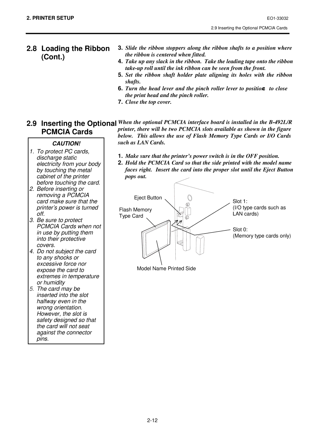
2.9Inserting the Optional When the optional PCMCIA interface board is installed in the
PCMCIA Cards | printer, there will be two PCMCIA slots available as shown in the figure | ||
below. This allows the use of Flash Memory Type Cards or I/O Cards | |||
| |||
CAUTION! | such as LAN Cards. |
| |
1. To protect PC cards, | 1. Make sure that the printer’s power switch is in the OFF position. | ||
discharge static | |||
2. Hold the PCMCIA Card so that the side printed with the model name | |||
electricity from your body | |||
by touching the metal | faces right. Insert the card into the proper slot until the Eject Button | ||
cabinet of the printer | pops out. |
| |
before touching the card. |
|
| |
2. Before inserting or |
|
| |
removing a PCMCIA | Eject Button |
| |
card make sure that the | Slot 1: | ||
| |||
printer’s power is turned | Flash Memory | (I/O type cards such as | |
off. | LAN cards) | ||
Type Card | |||
3. Be sure to protect |
| ||
|
| ||
PCMCIA Cards when not |
| Slot 0: | |
in use by putting them |
| ||
| (Memory type cards only) | ||
into their protective |
| ||
|
| ||
covers. |
|
| |
4. Do not subject the card |
|
to any shocks or |
|
excessive force nor | Model Name Printed Side |
expose the card to | |
extremes in temperature |
|
or humidity |
|
5. The card may be |
|
inserted into the slot |
|
halfway even in the |
|
wrong orientation. |
|
However, the slot is |
|
safety designed so that |
|
the card will not seat |
|
against the connector |
|
pins. |
|