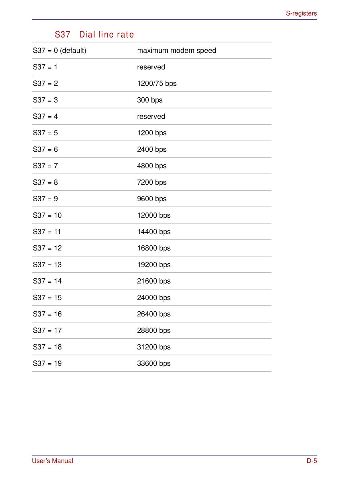
TOSHIBA
TECRA S3
Portable Personal Computer
Page
Product Name : TECRA S3
TECRA S3
Model number : PTS30
PTS30
FCC notice "Declaration of Conformity Information
Conformity Statement
Network Compatibility Statement
Germany
ATAAB AN005,AN006,AN007,AN009,AN010
and DE03,04,05,08,09,12,14,17
Greece
Pursuant to FCC CFR 47, Part 68:
Type of service
Telephone company procedures
If problems arise
Disconnection
Fax branding
The IC registration number of the modem is shown below
Canada: 4005B-ATHENS
Modem warning notice for Australia
Notes for use of this device in New Zealand
c/ Automatic calls to different numbers shall be not less than 5 seconds apart
■The correct settings for use with this modem in New Zealand are as follows:
ATB0 (CCITT operation) AT&G2 (1800 Hz guard tone)
AT&P1 (Decadic dialing make-breakratio =33%/67%) ATS0=0 (not auto answer)
ATS6=4 (Blind dial delay)
General conditions
An invoice for $NZ1237.50 will be sent under separate cover
Following information is only for EU-memberstates:
ManufacturerType
MATSUSHITAUJDA765
MATSUSHITAUJ-832
Table of Contents
Getting Started
Operating Basics
Page
The Keyboard
Power and Power-UpModes
HW Setup
Optional Devices
Troubleshooting
Disclaimers
Appendix A Specifications
Appendix B Display Controller and Modes Appendix C AT Commands
Appendix J TOSHIBA Anti-theftProtection Timer Glossary
Index
Preface
Chapter 8, Optional Devices, describes the optional hardware available
Disclaimers
The Appendixes provide technical information about your computer
Glossary
The Index quickly directs you to the information contained in this manual
Key operation
ABC
When procedures require an action such as
type face you see to the left
Display
Page
General Precautions
Page
Introduction
Software
Microsoft® Windows XP Professional
Documentation
Processor
Built-in
Disclaimer (CPU)*1
Memory
Slots
RTC battery
Clock (RTC) and calendar
AC adaptor
The AC adaptor provides power to the system
and recharges the batteries when they are low. It
DVD Super Multi
following resolutions:
XGA, 1024 horizontal × 768 vertical pixels
SXGA+, 1400 horizontal × 1050 vertical
pixels
Disclaimer (LCD)*4
Universal Serial Bus
(USB 2.0)
Docking
i.LINK™ (IEEE1394)
Infrared
Communications
Modem
LAN
Bluetooth
Wireless LAN
Disclaimer (Wireless LAN/Intel)*6
Wireless
This switch turns the Wireless LAN and
communication
Bluetooth functions on and off
TOSHIBA Assist
Press this button to launch an application
button
automatically. The default is TOSHIBA Assist
TOSHIBA
Intelligent power
supply
Battery save mode
Panel power on/off
Low battery
Hibernation
Standby
TOSHIBA Power
Saver
start
Fingerprint utility
Fn-esse
All Programs
TOSHIBA, point to Utilities and click Fn-esse
DVD Video Player
TOSHIBA SD
Memory Boot Utility
start, point to All Programs, point to TOSHIBA
point to Utilities and click SD Memory Boot
Utility
TOSHIBA Dual Pointing Device utility
TOSHIBA Mic Effect
point to Utilities and click TOSHIBA Mic Effect
Help
TOSHIBA RAID
Memory Card Format
to create a bootable SD memory card
CD/DVD Drive
Acoustic Silencer
of CD drive. You can either configure Normal
Advanced Port
Replicator
Wireless LAN Kit
Bluetooth Kit
Ultra Slim Bay options
Page
The Grand Tour
i.LINK (IEEE1394)
This port allows you to connect an external
device, such as a digital video camera for high
speed data transfer
Volume control
LAN jack
Link indicator
(green)
LAN active indicator
(orange)
This external monitor port lets you connect an
external video display
The S-Videocable carries video signal
ExpressCard slot
The ExpressCard slot can accommodate an
Figure 2-3shows the computer’s right side
Universal Serial Bus Two Universal Serial Bus ports are on the right
(USB 2.0) ports side. The ports comply with the USB 2.0 standard
Modem jack
lets you use a modular cable to connect the
Serial port
(USB 2.0) port
DC IN 15V jack
Parallel port
Battery lock
Slide the battery lock to release the battery pack
for removal
The battery pack powers the computer when the
AC adaptor is not connected. For detailed
Ultra Slim Bay lock
screw
Memory module
cover
HDD pack cover
Display hinge
easy-to-viewangles
Disable the
■System boot authentication and Single Touch Boot feature
Display screen
Stereo speakers
AccuPoint control
buttons
AccuPoint
Power button
LCD Sensor switch
DC IN
Power
Shut
Down Windows
Battery
Caps Lock
Arrow mode
Numeric mode
USB connector
Disk-In-Use
Indicator
Floppy disk slot
Eject button
Using optical media drives
Region codes for DVD drives and media
Code Region
1Canada, United States
2Japan, Europe, South Africa, Middle East
Formats
DVD-ROM&CD-R/RWdrive
DVD read
CD read
CD-Rwrite
Page
Page
Getting Started
■Select a work area that has:
■good air circulation
■a comfortable ambient temperature and relative humidity
■Keep the computer free of dust, moisture, and exposure to direct sunlight
■Do not operate the computer in close proximity to a mobile phone
■Leave ample ventilation room for the fan. Do not block the vents
■Always avoid abrupt changes of temperature or humidity
■Never place close to heat radiating appliances such as a heater
■Never place close to corrosive chemicals
■Always place this product on a flat surface
Seating and posture
Lighting
Consider the following suggestions regarding lighting your work environment:
■Use soft, indirect lighting
■Adjust the display panel to provide maximum visibility
Work habits
Strategic Rest Breaks
Other Things to Note
■Use a virus-checkprogram and make sure it is updated regularly
Always place the PC on a suitable
1.Connect the power cord to the AC adaptor
Page
This section describes how to turn on the power
Power indicators
1.Open the computer’s LCD display panel
2.Press and hold the computer’s power button for two or three seconds
Back
Windows End User License Agreement
Shut Down mode (Boot mode)
Turn Off Computer
Turn Off Computer
■Before entering Standby Mode, be sure to save your data
Benefits of standby
The standby feature provides the following benefits:
■Restores the previous working environment more rapidly than does hibernation
■You can use the panel power off feature
Press the power button. This feature must be enabled. Refer to the
Standby limitations
Standby will not function under the following conditions:
■Power is turned back on immediately after shutting down
■Memory circuits are exposed to static electricity or electrical noise
Benefits of Hibernation Mode
Starting Hibernation Mode
2.Select Turn Off Computer
Hibernate
Standby
Data save in Hibernation Mode
Certain conditions require that you reset the system. For example, if:
■You change certain computer settings
■An error occurs and the computer does not respond to your keyboard commands
■There are three ways to reset the computer system:
Esc
F12
In Touch with Tomorrow TOSHIBA
Page
Operating Basics
Click: Tap once
Double-click: Tap twice
Tap twice
Drag and drop:
Using the AccuPoint
2. Position a new cap on the peg and press it into place
The peg is square, so be careful to align the cap’s square hole with the peg
Logon to Windows and access a
Points to note about the Fingerprint Sensor
Do not scratch or poke the sensor with your nails or any hard or sharp objects
■Wash and dry your hands thoroughly
Clean the sensor with a
■Soaked or swollen finger (e.g. after taking bath)
■Injured finger
■Wet finger
Align the finger and sensor like the drawings
Points to note about the Fingerprint Utility
Please refer to the following procedures to back up
OmniPass
UserManagement
Set Up Procedure
Fingerprint Registration
Softex
OmniPass Enrollment Wizard
Enroll
Window Logon via Fingerprint Authentication
Fingerprint Authentication Procedure
Logon Authorization
Fingerprint System Boot Authentication
General
BkSP
Enable System Boot Authentication
PBA Settings
How to Enable Fingerprint System Boot Authentication Settings
1.Click on the System Settings tab in the OmniPass Control Center
Click on the
tab in the
2.Click on PBA Settings
Fingerprint utility limitations
How the Swipe the Finger
Connecting USB floppy disk drive
Disconnecting USB floppy disk drive
Safely Remove Hardware
USB floppy disk drive
Removing a module
Inserting a module
Tab
Loading discs
Page
Removing discs
To remove the CD/DVD, follow the steps below and refer to figure
How to remove CD/DVD when the disc tray will not open
Writable discs
Special features
Before writing or rewriting
Please observe the following points when you write or rewrite the data
CD-R:
TAIYO YUDEN CO., LTD
MITSUBISHI CHEMICAL CORPORATION
When writing or rewriting
Note the following when you write or rewrite a CD-Ror CD-RW
■Do not perform any of the following actions:
■Change users in the Windows XP operating system
■Start a communication application such as a modem
Important message
Disclaimer
CD-RW: (Multi-Speedand High-Speed)
CD-RW: (Ultra-Speed)
DVD-R:
DVD+R:
DVD+R DL:
DVD-RW:
DVD Specifications for Recordable Disc for Version 1.1 or version
DVD+RW:
In writing to a
■Be sure to connect the AC adaptor before you write or rewrite
■Operate the computer in the full-powermode. Do not use power-savingfeatures
■Do not perform any of the following actions when writing or rewriting:
■Use the Audio/Video control button to reproduce music or voice
RecordNow! Basic for TOSHIBA
Note the following limitations when you use RecordNow!:
■DVD-Videocannot be created using RecordNow
■DVD-Audiocannot be created using RecordNow
Data Verification
Options
DLA for TOSHIBA
When using WinDVD Creator Platinum
Performance and Maintenance
System
Advanced
Change
■Make sure that your computer is running on AC power when using WinDVD Creator
■Operate the computer at Full Power. Do not use power-savingfeatures
While you are editing a
■WinDVD Creator cannot edit or play copy protected content
■Do not change display settings while using WinDVD Creator
■WinDVD Creator cannot export to DVD-Audio,VideoCD or miniDVD format
WinDVD Creator can write
3.About Disc Manager
■WinDVD Creator can edit one play list on a disc
Using the Disc Manager, you can edit
Floppy disks
Volume Control
Accessories
Entertainment
Volume Control
Microphone level
4.Click Options and select Advanced Controls
5.Click Advanced
Microphone Boost
SigmaTel Control Panel
To select a region, follow the steps below
Modem Region Select
2.The Region Selection icon will appear in the Windows Task Bar
Select a region from the region menu or a telephony location from the
Properties menu
Setting
AutoRun Mode
Open the Dialing Properties dialog box after selecting region
Location list for region selection
1.Plug one end of the modular cable into the computer’s modem jack
2.Plug the other end of the modular cable into a telephone jack
Do not pull on the cable or move the computer while the cable is connected
■Modem speed is slow or communication is interrupted
■Skips may occur in sound
Disconnecting
To disconnect the internal modular cable, follow the steps below
2.Disconnect the cable from the computer’s modem jack in the same manner
■Theoretical maximum speed: 54Mbps (IEEE802.11a, 802.11g)
■Theoretical maximum speed: 11Mbps (IEEE802.11b)
Security
Bluetooth wireless technology
Bluetooth wireless technology has the following features:
Worldwide operation
Radio links
Product Support:
Wireless communication Indicator
Indicator status
Indication
Indicator off
Wireless communication switch is set to off
Connecting LAN cable
To connect the LAN cable, follow the steps below
LAN Active
Link
Disconnecting LAN cable
Using the Hard Disk Drive (HDD) Protection
Make sure all disk activity has ended before moving the computer. Check the
■Turn off the power to the computer
■Disconnect the AC adaptor and all peripherals before moving the computer
■Close the LCD display panel. Do not pick up the computer by its display panel
Taskbar Icon
State
Icon
Description
Normal
TOSHIBA HDD Protection Properties
HDD Protection setting
HDD Protection
Detection Level
Details
Detection Level Amplification
HDD Protection Message
Page
The Keyboard
Soft keys: Fn key combinations
Emulating keys on enhanced keyboard
F10
F11
ScrLock
Sound mute:
Instant security:
Power save mode:
Display selection:
LCD
Wireless setting:
Disabled Wireless Communication Switch
key while holding down the
key. The chosen function is executed when the
keys are released
To reduce the icon size on the desktop or the application window, press the
key
This key activates the Windows start menu
This key has the same function as the secondary mouse button
Turning on the overlays
Arrow mode
Numeric mode
Temporarily using normal keyboard (overlay on)
Temporarily using overlay (overlay off)
Temporarily changing modes
With the overlay on:
1.Hold down Alt
2.Using the overlay keys, type the ASCII code
1.Hold down Alt + Fn
Page
Power and Power-UpModes
not
DC IN off
Battery, DC IN
Battery indicator
Flashing orange
DC IN indicator
supplying proper power to the computer
Indicates a problem with the power supply. Plug
the AC adaptor into another power outlet. If it still
does not operate properly, contact your dealer
Extending battery life
High capacity battery pack (option)
Real Time Clock (RTC) battery
Safety precautions
Warning:
Caution:
Note: Provides important information
Page
■Offensive or unusual odor
■Excessive heat
■Discoloration
■Deformation
■Smoke
Note
Charging the batteries
Procedures
Time
Charging time (hours)
Maximizing battery operating time
Battery charging notice
The battery may not charge right away under the following conditions:
Monitoring battery capacity
Maximizing battery operating time
Retaining data with power off
Retention time
Extending battery life
The battery pack is classified as a consumable item
To remove a discharged battery pack, follow the steps below
1.Save your work
2.Turn the computer’s power off. Make sure the Power indicator is off
3.Remove all cables connected to the computer
User Password
start ->All Programs ->TOSHIBA ->Utilities ->PasswordUtility
User Password and User Token
User Password field
■Set (button)
■Delete (button)
■Change (button)
■Owner String (text box)
Supervisor Password
C:\Program Files\Toshiba\Windows Utilities\SVPWTool\TOSPU.EXE
This utility lets you do the following:
■Register, delete or change the Supervisor Password
■Create or invalidate a Supervisor Password token
Windows utilities
Hot keys
HW Setup
Setup
Power On Display
Boot Priority Options
Page
HDD Priority Options
USB Memory BIOS Support Type
External Keyboard Fn key
Wake-upon Keyboard
Dynamic CPU Frequency Mode
Wake-upon LAN
Built-inLAN
Device Configuration
Parallel Port Mode
USB KB/Mouse Legacy Emulation
USB-FDDLegacy Emulation
Notes before using the BIOS Setup
•Password
•Hard Disk Drive Password
•Security controller
Starting and Ending the BIOS Setup Program
Ending the BIOS Setup Program
Ending the BIOS Setup Program Halfway
Exit without saving? (Y/N)
Execute-DisableBit Capability
Available
Security controller
SYSTEM SETUP (2/2)
TPM
Clear TPM Owner
Clear TPM Owner
Page
Optional Devices
Inserting a PC card
Removing a PC card
Inserting an ExpressCard
Removing an ExpressCard
Formatting an SD memory card
SD memory card Format
Inserting an SD card
To insert an SD card, follow the steps below
1.Insert an SD card in the SD card slot
■Make sure the SD card is oriented properly before you insert it
Removing an SD card
To remove an SD card, follow the steps below
2.Point to SD card and click
3.Push in the SD card and release it to pop the card out slightly
SD card care
Creation of a boot disk
Installing memory module
5. Slide your fingernail or a thin object under the cover and lift it off
System Properties
General
Removing memory module
7.Grasp the module by the sides and pull it out
8. Seat the memory module cover and secure it with one screw
10.Turn your computer over
Removing the hard disk drive pack
Installing the hard disk drive pack
Page
Page
Using the TOSHIBA Assist button
a.Click start and click Control Panel
Click
b.Double-clickthe Display icon to open the Display Properties window
c.Click the Settings tab and click the Advanced button
d.Click the GeForce Go 6600 tab, click Device Settings and click
d.Click OK
e.Click OK in the Display Properties screen
■Digital video cameras
■Hard disk drives
■MO drives
2.Point to i.LINK (IEEE1394) device and click
Page
Parallel/Printer
TOSHIBA HW Setup
10.Set the Parallel Port Mode and press OK
Add Print Wizard
Add Printer
1.Turn the computer so the left side faces you
2.Align the holes for the security lock and attach the lock
Troubleshooting
Preliminary checklist
Analyzing the problem
PrtSc
Software
Next, check any error messages in the operating system documentation
Hardware
■ System start-up
■ Dual Pointing Device
Self test
In Touch with Tomorrow
TOSHIBA
Power
Overheating power down
AC power
ProblemProcedure
Battery
Page
Real Time Clock
1.Press F1 key. BIOS setup will boot up
2.Set the date in System Date
3.Set the time in System Time
4.Press End key. Confirmation message will appear
Internal LCD display panel
Hard disk drive
Page
Page
USB floppy disk drive
SD card
PC card
ExpressCard
Infrared port
Dual Pointing Device
Touch Pad/AccuPoint
click Control Panel, click Printers and Other
Mouse
Mouse Properties and click Dual Pointing
USB mouse
On-screenpointer does not respond to mouse operation
Make sure the mouse is properly connected to the USB port
Double-clickingdoes
not work
Set the Enable System Boot Authentication
Control Center
USB device
Memory expansion
Beep sounds
(Two beeps, a dash and a dot, for a defective memory module in slot A
When both beeps sound, both memories in slot A and B are defective.)
If an incompatible module has been installed, follow the steps below
External monitor
i.LINK (IEEE1394) device
Add
Modem
Refer to Appendix C, AT Commands and Appendix D, S-registers
Communication
Make sure the computer’s internal modem
software can’t initialize
LAN
Bluetooth
Printer
TV output signal
Disposing of PC and PC batteries
■Selecting Delete for a target file
■Putting files in the Recycle Bin and emptying the Recycle Bin
■Reformatting the media
■Reinstalling an operating system from the recovery CD-ROM
Where to write
Outside of Europe
In Europe
Australia
Germany & Austria
United States of America
United Kingdom
The Rest of Europe
Page
Disclaimers
CPU performance may also vary from specifications due to design configuration
Page
Page
Specifications
Power Requirements
Computer
Built-inModem
Network control unit (NCU)
Type of NCU
Transmitting level
Receiving level
Input/output
impedance
Error correcting
Page
Display Controller and Modes
Table1 Video modes (VGA)
Video mode
Type
Resolution
Character
Table1 Video modes (VGA) continued
Video
mode
Table 2 Video modes (XGA model)
CRT
colors
frequency (Hz)
only)
Table 2 Video modes (XGA model) continued
Page
Table 3 Video modes (SXGA+ model)
Table 3 Video modes (SXGA+ model) continued
Page
Page
AT Commands
Bn Communication standard setting
B15
B16 Selects Bell 103J when the modem is at 300 bps (default). Result Codes:
OK n=0,1,15,16 ERROR Otherwise
Dn Dial
Hook control
Request ID information
Ln Monitor speaker volume
Mn Monitor speaker mode
Nn Modulation handshake
Return on-lineto data mode
Select pulse dialing
Result code control
NO CARRIER
T Select tone dialing
Vn DCE response format
Result code selection, call progress monitoring
Command
Dial tone
Dial tone detect
Disabled: The modem dials a call regardless of whether it detects a dial tone
Busy tone detect
Disabled: The modem ignores any busy tones it receives
Enabled: The modem monitors for busy tones
&D2
&D3
&F Load factory settings
&Gn V.22bis guard tone control
&G0
&Tn Self-testcommands
&T0 Abort. Stops any test in progress
&T1
OK n=0 CONNECT n=1 ERROR Otherwise
&V Display Current Configuration
\N3 V.42, MNP, or buffered (default)
\N4
\N5
\N7
OK n=0,1,2,3,4,5,7 ERROR Otherwise
Result Codes: OK n=0,3 ERROR Otherwise
S-registers
S1 Ring counter
S2 AT escape character (user defined)
S3 Command line termination character (user defined)
S4 Response formatting character (user defined)
S5 Command line editing character (user defined)
Default: 8 (backspace)
S6 Wait before dialing
Units: seconds
S7 Connection completion time-out
S8 Comma pause time
S11 DTMF dialing speed
S12 Escape guard time
S37 Dial line rate
The result code summary
Result Code
Numeric
Page
Page
Function
Transmission speed
(minimum)
Reception only
Table E-1Result codes for a V.90 connection
V42bis
NoEC
-V90
-V90=0
-V90=1
Page
Wireless LAN
R-FFrequency
■ Band 5GHz (5150-5850MHz) (Revision A)
■ Band 2.4GHz (2400-2483.5MHz) (Revision
B, G)
Modulation
102457*1
122467*2
132472*2
*1 Factory-setdefault channels
For Wireless LAN cards installed in wireless clients that operating in a
Page
TOSHIBA RAID
Use the following procedures when manually setting up Windows
Before Setting Up Windows
Creating the TOSHIBA RAID Driver Disk
1.Connect the USB floppy disk drive and insert a floppy disk
menu, select
Page
Starting the BIOS Setup Program
Check system. Then press [F1] key
Modifying the BIOS
Current State
Create State
Ending the BIOS Setup Program
Page
Bluetooth wireless technology Interoperability
Page
General
European Union (EU) and EFTA
Canada - Industry Canada (IC)
USA-FederalCommunications Commission (FCC)
-Reorientor relocate the receiving antenna
-Increasethe distance between the equipment and the receiver
-Consultthe dealer or an experienced radio/TV technician for help
Caution: Exposure to Radio Frequency Radiation
Taiwan
Article 17 Any use of low power radio frequency electric machinery shall
1. Sticker
Please put the following sticker on computer incorporating this product
2.Indication
The indication shown below appears on this equipment
(1)2.4 : This equipment uses a frequency of 2.4 GHz
(2)FH : This equipment uses FH-SSmodulation
(3)1: The interference range of this equipment is less than 10 m
Device Authorization
Austria
Belgium
Cyprus
Czech Republic
Denmark
AC Power Cord and Connectors
France:
Switzerland:
Germany:
United Kingdom:
Europe
TOSHIBA Anti-theftProtection Timer
Page
Glossary
IrDA
IRQ:
KB:
LCD:
LED:
analog signal:
ANSI:
antistatic: A material used to prevent the buildup of static electricity
application:
ASCII:
bus: An interface for transmission of signals, data or electric power
byte:
capacity:
card: Synonym for board. See board
CardBus: An industry standard bus for 32-bitPC cards
compatibility:
components:
computer program:
computer system:
configuration:
delete:
dialog box:
disk drive:
disk storage:
display:
escape:
2) A means of aborting the task currently in progress
escape guard time:
execute: To interpret and execute an instruction
Extended Capability Port:
hard disk drive (HDD):
hardware:
hertz:
hexadecimal:
host computer:
KB: See kilobyte
keyboard:
kilobyte (KB):
level 2 cache: See cache
cache
mode:
modem:
motherboard:
nonvolatile memory:
numeric keypad overlay:
password:
pel:
peripheral component interconnect: An industry standard 32-bitbus
An industry standard
32-bit
restart:
RGB:
RJ11: A modular telephone jack
RJ45: A modular LAN jack
SCSI:
terminal:
TFT display:
Touch Pad:
TTL:
Universal Serial Bus:
Page
Index