Page
Table of Contents
Introduction
Contents of the package
» The features you’ll enjoy include
Options
» Precautions
Important Information
» Warnings and Safety Precautions
Important Information
» To avoid damage and prolong operating life
» Plasma monitor cleaning procedure
Limited Warranty
What is Covered Under the Terms of this Limited Warranty
Important Warranty Registration
Effective Warranty Date
Limited Warranty
RIGHTS, Limits and Exclusions
Additional Information
Vidikron
HOW to Attach Options to the Plasma Monitor
Ventilation Requirements for enclosure mounting
Part Names and Functions
» Front View
AUDIO1, AUDIO2, AUDIO3
» Rear View / Terminal Board
External Control
Rear View / Terminal Board
Y Cb/Pb
» Remote Control
Display
Remote Control
Displays the source settings on the screen
Light
» Battery Installation and Replacement
» Handling the remote control
» Operating Range
Installation
Video
Installation
» Connecting Your PC or Macintosh Computer
» Connecting Your VCR or Laser Disc Player
» Connecting Your DVD Player
» Pin Assignment and Signal Levels for 15 pin RGB analog
RGB
Basic Operations
» Power
» Volume
» Mute
To cancel the off timer
» Timer OFF
To set the timer off
Basic Operations
Aspect Ratio Controls
» Aspect Ratio Operations Manual
Intelliwide mode
Aspect Ratio Controls
» Aspect Ratio Operation with Computer Signals
Within 3 seconds
OSD On Screen Display Controls » Menu Operations
Change the adjustments or the settings that are stored
Button on the remote control to return to the main menu
Memory. The change is stored until you change it again
Adjust
OSD On Screen Display Controls
Image
HD Type
Language
Adjusting the picture
» Picture Adjust Menu
Use the and buttons to adjust the contrast
To set to Factory
Example Setting the Factory mode
Once the adjustment is completed
Types of picture modes LW BLK1
Reducing noise in the picture
Once the setting is completed
Types of noise reduction
See below to set White Balance Adjust
Setting the White Balance
Adjusting the color to the desired level
Adjusting the white balance
Adjust the white balance using the and buttons
Changing the Gamma Curve
Making the Dither adjustments
Gamma Curve settings
Dither settings
Adjusting the colors
Diffuse
Color Chart settings
» Audio Setup Menu
To continue adjusting the audio
Audio setup menu
Example Setting Audio INPUT1 to Video
Setting the allocation of the audio connectors
To set the Audio INPUT1 to VIDEO2
To adjust the vertical position
» Image Options Settings Menu
To select a mode
To continue making other computer image adjustments
Restoring the factory defaults settings
Adjusting the Computer
Adjusting the position of the image
OFF
Setting the on-screen menu
» Setting 1 Settings Menu
To set the Display OSD to OFF
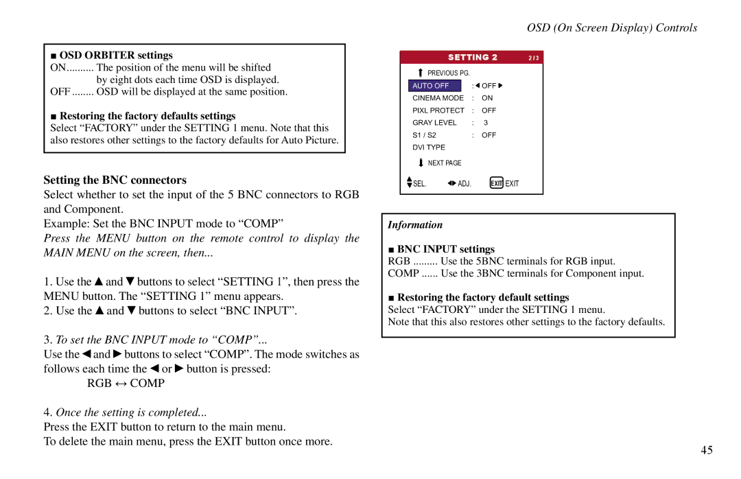
OSD Orbiter settings
Setting the BNC connectors
To set the BNC Input mode to Comp
BNC Input settings
To set the RGB select mode to Auto
It is set to RGB and can not be adjusted
Example Setting the RGB Type mode to Auto
RGB Type modes
Example Setting the 1080B mode to
To set the HD Type mode to 1080B
Input Skip settings
Setting the Input Skip
To set the Input Skip mode to OFF
HD Type modes
Resetting to the default values
Use the and buttons to select ON, then press the Menu button
Setting the Auto Off for computer images
» Setting 2 Menu
To turn the Auto Off function on
Power / Standby indicator
Setting the picture to suit the movie
Perform Steps 1-2 of Pixl PROTECT, then
Orbiter settings
Orbiter
Perform Steps 1-3 of ORBITER, then
Adjust the Orbiter function manually
Orbiter Function settings
Inverse
Perform Steps 1-3 of INVERSE, then
Setting the time for INVERSE/WHITE
Setting the time
Press the Exit button to return to the Pixl Protect screen
Image Sweep
Example Setting Image Sweep to on
Perform Steps 1-3 of Image SWEEP, then
Press the Exit button to return to the Image Sweep screen
Setting the Sidebar Lev. for the sides of the screen
Soften settings
Soften
Setting the screen size for S1/S2 video input
To adjust the Sidebar LEV
Use the and buttons to adjust the Sidebar LEV
Sidebar LEV. settings
Black Level settings
S1/S2 Settings
PLUG/PLAY Settings
Perform the following operations
Preset Time
» Setting 3 Menu
Using the timer
Perform Steps 1-2 of TIMER, then
DAY
Preset Time settings
Daylight Saving Time
Hour
Use the and buttons to select Program
Program Timer
ON/OFF Hour
To set the Default Input to VIDEO2
Setting the Default Input
Use the and buttons to select VIDEO2
→ RGB3 ↔ RGB1 ↔ HD2 ↔ HD1 ←
Input Select settings
→ RGB3 ↔ RGB2 ↔ RGB1 ↔ HD1 ←
Enabling/disabling the front panel controls
Control Lock settings
Example Setting OFF Perform the following operations
To set the IR Enable to OFF
To set the Control Lock to on
Loop OUT settings
Loop Out Setting
IR Enable settings
To set the Loop OUT to on
ID Number settings
ID Number Setting
To reset back to ALL Press the Clear button
When the ID Number has been set
Video Wall Setting
Use this feature to configure a 2×2 or 3×3 video wall
Divider
Set the 2x2 or 3x3 video wall Example Setting
Set the position of each display Example Setting
Perform Steps 1-2 of Video WALL, then
Press the Exit button to return to the Video Wall screen
DISP. Mode
Video Wall Position settings
Auto ID
Auto ID settings
Use
On Delay Power on delay
On Delay settings
Video Wall
LUM SET Link settings
Repeat Timer Reptr
Use the and buttons to select Reptr Time
Reptr Time settings
Divider Source
Language settings English German French Spanish Italian
» Language Settings Menu
Setting the language for the menus
To select Deutsch
» Video Standard Menu
Setting the video signal format
To select 3.58NTSC
Once you have checked the frequency
» Signal Info. Menu
Video standard formats
Connections
External Controls
Application
Communication Parameters
External Controls
Command
Communication Format
Unit ID 1 and Unit ID
Command Reference List
CMD1 CMD2 LEN
Power OFF
Power on
Input Switch Change
Audio Mute OFF
Volume Gain Data
Audio Mute on
Contrast Gain Data
Bright Gain Data
Sharpness Gain Data
Color Gain Data
Tint Gain Data
Image MEM. Select
White BAL. Select
RED Gain Data
Green Gain Data
VID NR Mode SET
Blue Gain Data
Bass Gain Data
Treble Gain Data
Balance Gain Data
Aspect Ratio Select
Shift Gain Data
Size Gain Data
Phase Gain Data
Clock Gain Data
OSD Select
OSD ADJ. Gain Data
Auto OFF Select
Cinema Mode SET
Sidebar LEV. SET
33 RGB3 ADJ. Select
Pixl Protect SET
Inverse SET
Image Sweep SET
Factory
Audio Select SET
BNC Select
RGB Select
Language Select
HD Select
100
Frequency Request
Video Standard Select
101
Input Mode Request
102
Video ADJ Request
103
Auto Select Request
104
Model Name Request
Failure Mode Request
105
Computer input signals supported by this system
Table of Signals Supported
106
Table of Signals Supported
107
PAL625P
Troubleshooting
109
Troubleshooting
110
Specifications
111
Specifications
112
Dimensions
113
Dimensions
114
VP-60
115
RUMA-010550