Page
Safety Notice
Precautions
Horsepower RMS Symmetrical Ampheres
Page
Change from Main Source to 2nd Source
Parameters
Sets the off delay timer for the digital output
Table of Contents
Troubleshooting
Customizing for Your Application
Appendix B Options & Kits
Appendix C RS485 Protocol
Chapter
Getting Assistance from Baldor
Page
General Information and Ratings
Identifying the Drive by Model Number
VS1MD Drive Ratings, Model Numbers and Frame Sizes
Storage Guidelines
Installing the Drive
General Requirements for the Installation Site
Operating Conditions
Minimum Mounting Clearances
Mounting Dimensions for the VS1MD Drive
Drive Dimensions and Weights Frame a
Frame Size B 230V/460V 100 95.5 128 120 130
Frame Screw Size Screw Torque
Mounting the Drive
Protecting the Drive from Debris
Watts Loss Data
Model # Frame Watts Loss
Power Wiring
Grounding the Drive
Grounding Guidelines
Grounding Procedure
RFI Filter Grounding
Connecting Peripheral Devices to the VS1MD Drive
Power Terminal Wiring
Power Terminal Wiring
Specifications for Power Terminal Block Wiring
Recommended Breakers
Recommended Fuses and AC Reactors
Reflected Wave Protection
Page
Control Wiring
Stop Circuit Requirements
Motor Start/Stop Precautions
Terminal Wiring Control I/O
Description
Control Terminal Specifications
Source/Sync for Input Control Wiring
Maximum Control Wire Length Recommendations
I/O Wiring Recommendations
Technical Specifications
Keypad Components
Display Description
LED Descriptions
Key Descriptions
Operation Mode
About Parameters
Moving Between Parameter Groups
Procedure Sample Display
How Parameters are Organized
Terminal group Function Group
Changing Between Parameters Within a Group
Using the Jump Code
Modifying the Value of a Parameter
Modifying Parameter Values
Monitoring Display Parameters
Display Group
Reviewing the Fault Status in the Display Group
Resetting the Parameters to Factory Default
Overview
Parameter Number
Parameter Name
LED Display
Display Group Parameters
Displays the present DC bus voltage level
Software Version Range Default
NOn Current Fault Display Range
P0 Jump Code Range30 Default AccessTunable
Basic Program Group Parameters
P30 Motor HP Select Range
P32 Motor Rated Current Range 50 Amps
P37 Frequency Command Range 400 Hz Default AccessTunable
P35 Frequency Low Limit Range P36 Hz Default
P36 Frequency High Limit Range 400 Hz Default
P38 Stop/Start Source Range
P38 Stop/Start Source
Default Access
P39 Stop Type Range
Access Tunable See Also
P40 Frequency Setting Method Range
P41 Accel Time P42 Decel Time Range 000 sec Default
P46 Drive Start/Stop Source Range
AccessTunable See Also
P47 Frequency Setting Mode Range
T0 Jump Code Range 0 Default Access Tunable
Terminal Parameters
= Preset Speed Input Bit
= Preset Speed Ramp Bit 10 = Preset Speed Ramp Bit
14 = Reserved Reserved
Frequency P4A contact P5B contact Run command
Filtering Time Constant for Multi-function input terminal
Range Default Access Tunable See Also T1-t8
Decrease Down
Parameter Preset Speed Preset Speed Input Bit
6000 Sec
Decel
Access Tunable See also T32-t33
T32 Digital Output MO T33 Relay Output 3A 3C Range
T35 Criteria for Analog Input Signal Loss Range
Sets the minimum voltage of the Analog Input V1 input
Sets the minimum current of the Analog 0-20mA I Input
T57 Keypad Error Output
Relay Output Digital Output Bit
T60 Inverter Number Range Default Access Tunable See Also
T62 Frequency Loss Mode Range
T59 Communication protocol select Range
T61 Baud Rate Range
T63 Frequency Loss Wait Time Range
T64 Communication Time Setting Range
T65 Parity/Stop Bit Setting Range
Access Tunable
F0 Jump Code Range Default Access Tunable
F1 Forward/Reverse Run Disable
Function Group 1 Parameters
F2 Accel Pattern F3 Decel Pattern
F10 DC Brake Voltage Range
DC Brake start frequency
DC Brake wait time
F13 DC Brake start time Range
F11 DC Brake Time Range
F12 DC Brake start voltage Range
F27 Torque Boost select Range
F14 Time for magnetizing a motor Range
F20 Jog Frequency Range
See Also F27-F29
F30 V/F Pattern
100 %
F40 Energy Savings Level Range
F39 Output voltage adjustment Range
F50 Electronic thermal select Range Default Access
F53 Motor cooling method
F51 Electronic thermal level for 1 minute Range
F52 Electronic thermal level for continuous Range
Default Access Tunable
F56 Default
F54 Overload Warning Level Range
F55 Overload warning time Range
Parameter Descriptions
F63 Save Up/down frequency Range Default Access
F60 Stall prevention level Range
Parameter Descriptions
H0 Jump Code Range 0 Default Access Tunable
Function Group 2 Parameters
120
H7 Dwell Frequency Range
H10 Skip Frequency Enable Range 0 Default
See also H11-H16
= P41 + P41⋅ H17 + P41⋅ H18 = P42 + P42 ⋅ H17 + P42 ⋅ H18
H19 Phase Loss Protection Range 0 3n Default Access Tunable
H22 Speed Search Select Range 0 Default
H27 Auto Restart Time Range
H26 Auto Restart Attempts Range Default Access
H24 Speed Search P Gain H25 Speed Search I Gain Range
H32 Slip Frequency Range
See Also P33, H40
H34 No Load Motor Current Range
H36 Motor Efficiency Range
H39 Carrier Frequency Select Range
H40 Control Mode Select
H37 Load Inertia Rate Range
H42 Stator Resistance Rs Range
H41 Auto-Tuning Range 0 Default
See also H40, H42, H44
H44 Leakage Inductance Lσ Range
See also H40, H41, H42
H45 Sensorless P Gain H46 Sensorless I Gain Range
H50 PID Feedback Selection Range
Parameter Descriptions
H70 Frequency Reference for Accel/Decel Range 0 Default
H71 Accel/Decel Time Scale Range 0 Default Access Tunable
H72 Power-On Display Range 0 Default
H74 Gain for Motor RPM Display Range
See Also D1, H72
H75 DB Resistor Select Range 0 Default
See Also H76
H77 Cooling Fan Control Range Default Access
Dec
VS1MD
H91 Parameter Read H92 Parameter Write Range Default
H93 Parameter Initialize Range 0 Default
Page
Frequency Mode
Keypad Frequency Setting
Frequency Setting via -10 to +10V Input
T49
Group Code Parameter Name Setting Range Initial Unit
Frequency Setting via 0 to 20 mA Input
Frequency Setting via -10 to +10 Voltage Input + 0 to 20 mA
Frequency Setting via 0 to 10 + 0 to 20 mA Input
Frequency Setting via RS 485 Communication
Operating Command via RS485 Communication
UP-Down
Up/down frequency saved
Wire
PID Control
PID Block Diagram
Auto-tuning
Sensorless Vector Control
Factory default by motor ratings
Speed Search
Following table shows 4 types of Speed search selections
Example Speed search during Instant Power Failure restart
Self-Diagnostic Function
How to Use Self-Diagnostic Function
Parameter Read/Write
Parameter Read
Password Registration
Password for the first time
Parameter Initialization / Lock
Parameter Write
Changing password. Current PW 123 New PW
Parameter Lock
Locking the user-set parameters
Unlocking the user-set parameter
Multi-function Output Terminal MO and Relay 3AC
FDT-4 FDT-5
FDT-1
FDT-2
FDT-3
Parameter Name
11.5
Over Voltage Trip Ovt
Command Loss
Low Voltage Trip Lvt
Inverter Heatsink Overheat OHt
During Operation
Cooling Fan Trip Alarm
Wait Time for Run Signal Input
Fault Output
Control
Setting
Accel/Decel
Control Block Diagram
Frequency and Drive Mode Setting
Keypad or Remote keypad 10 ~ +10 ~ 20 mA
Page
Troubleshooting
Determining Drive Status Using the STP/FLT LED
Fault Codes
3A/3B MO
Manually Clearing Faults
Automatically Clearing Faults Auto Restart Feature
Fault Descriptions
Frequency reference is lost
Fault Correction
Cooling system has Check for foreign
Overload Protection
Page
Terminal Strip Input
Environment
Control
MG, External Power Supply Ground Terminal
Terminal Strip Outputs
Appendix B
Remote Keypad and Cable Model Numbers
Installation
Remote Cable 2M,3M,5M
Options & Kits
3 VS2MD-NM1B
Conduit Kit
Conduit Kit Model Numbers
4 VS1MD-NM1C 5 VS1MD-NM1D
Installation refer to legends in diagram
Preparation
6.2 VS1MD-NM1D Preparation
Installation
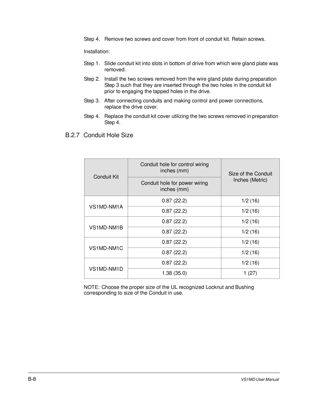
Conduit Hole Size
Braking Resistor
Page
Introduction
Features
Before Installation
Specifications
Performance Specifications
Hardware Specifications
Communication Specifications
Installation
Connecting the Communication Line
Operation
Computer and Inverter Connection
Basic Format
Communication Protocol MODBUS-RTU
Communication Protocol LS Bus
ASCII-HEX
Detail Communication Protocol
Request for Read
2.2 Acknowledge Response
2.3 Negative Acknowledge Response
Negative Response
Request for Monitor Register
2.8 Acknowledge Response
2.9 Negative Acknowledge Response
2.13Error codes
Action Request for Monitor Register
2.11Acknowledge Response
2.12Negative Response
Troubleshooting
Check Points Corrective Measures
Ascii Code List
Miscellaneous
DIF
Technical Writing Internal Use
Page