0118 96 55
LRU4240
0118 96 56
0870 90 10
Switzerland Spain
Austria Sweden
France Italy
Deutschland Denmark
Dual Trunk E1 Router User’s Guide Technical 0118 96 56
Copyright ISO Compliance
Customer Information
Regulatory Information
Preface
Access Configuration
Bridging Configuration
Firewall Configuration
Troubleshooting
Appendix B, Cable and Connector Pin Assignments 101
Dual Trunk E1 Router
Dual Trunk E1 Router
Dual Trunk E1 Router
Dual Trunk E1 Router
Index 203
Dual Trunk E1 Router
Dual Trunk E1 Router
Dual Trunk E1 Router
Dual Trunk E1 Router
SALES0870 90 10
Audience
Preface
Organization
Conventions
Symbols
Telephone 0118 96 56
Typeface or Symbol Purpose Example
Typography
Black BOX Technical Support
All suggestions and comments are appreciated
Returning a Unit
Send US Your Comments
Black Box
Product Overview
Product Overview
Redundancy
Applications
Dual independent links application
Load balancing
Multilink application
Monitoring Higher Protocol Layers
Monitoring the Entire WAN Protocol Stack
Provided with Level 2 Option for Level 2
Unpacking and Checking Equipment
Installation
Package Contents
Before YOU Install Site Requirements
Installing the Dual Trunk E1 Router
Installation
Installation Using AC Power
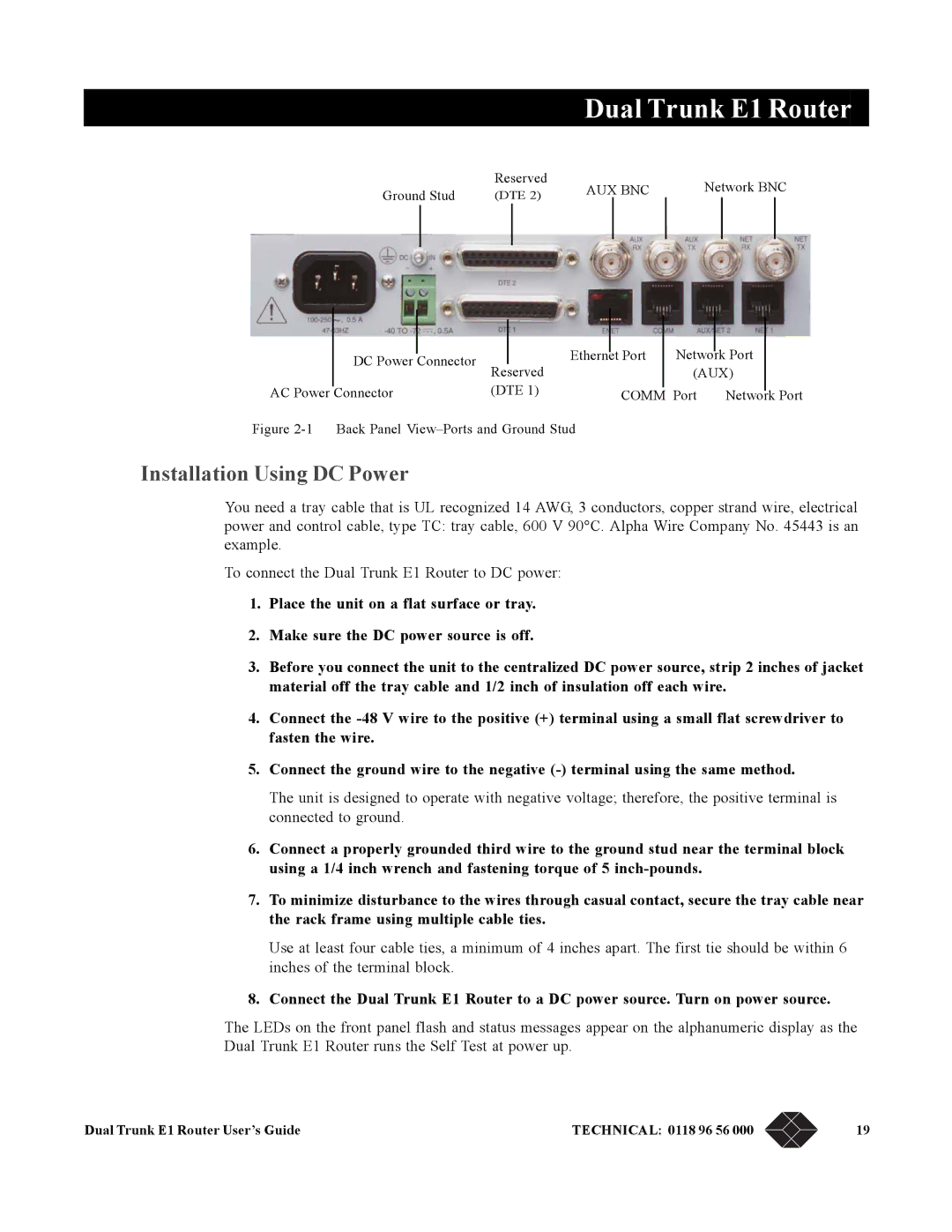
Back Panel View-Ports and Ground Stud
Installation Using DC Power
Dual Trunk E1 Router
Navigating the Front Panel
Terminal Setup
Button Function
Description
7 8 9 j k l m
EFS Field
Default Display
Configuration Options
Front Panel Display
Self Test appears on the display
Following table lists the configuration options
Test Options
Option Definition
To Stop a Test
Terminal User Interface Mode
Monitor Option Write Access
Monitor Options
Terminal Interface Navigation
Setting a Menu Parameter
Attaching to a Terminal
Hyperterm Windows Setup
Using the Ethernet port as management interface
Using Terminal Software
Terminal Setup
Type a File Name, choose an icon then click OK
COM1 Properties box appears for Port Settings
Set the following
Logging On from a Terminal
Logging Off from a Terminal
Adjusting Comm Port Settings
Logging on from a Telnet Connection
Assigning User Passwords
Configuring Access Rights
Enter the Normal User or Super User password
Overview of Access Configuration
Access Configuration
Procedure Description Menu Reference
Dual Trunk E1 Router
Procedure Steps
Configuring LAN Interface
Setting ID, DATE, TIME, and Network Timing
Unit Configuration− Menu 4A
Main/Alt Sync INT, NET1, NET2
Date
Configuring Timeslot Allocations
Net Configuration and Status
Set allocation type to Contiguous
Configuring Single Link PPP Interface
Configuring WAN Protocol
Procedure Purpose
Configuring independent PPP links Interfaces
Configuring Mlppp Interface
Configuring PPP Protocol Parameters
Configuring Frame Relay DLCIs
Configuring single link Frame Relay
Configuring independent Frame Relay links
Configuring Multilink Frame Relay
Mapping DLCIs to IP Addresses
Configuring Slip
Manual Dlci configuration
ProcedureSteps
Configuring Radius Authentication
Configuring TUI Access Rights
Select Authentication Response Timeout
Select Authentication Retries
ENABLING/DISABLING Traffic Monitoring
Configuring Snmp
Configuring Time and Date Synchronization
Select Menu-$K
Configuring Dhcp
Overview of the Configuration
Bridging Configuration
Bridging Configuration
Vlan Forwarding support
Managing the unit in Bridging mode
Bridging Application Examples
Dual Trunk E1 Router
Set Bridge Route Aging Time in seconds
Configuring Bridging
Configuring static MAC Bridge Routes
Select Menu-$A
Select the Action field of the entry you want to delete
Displaying MAC to Port Map Table
Select Menu-$GA
Set the Action field to Add
Configuring the Firewall
Routing Configuration
Configuring Default Gateway
Configuring Routing Mode
Configuring Static Routes
Set the Action field 5 to Add
Select the Destination IP field of an inactive route
Configuring NAT
Configuring Dynamic Routing
Load balancing over independent links
Menu Description
NAT Configuration menus
Select menu-$JE
Configuring NAT for single link ISP
Select menu-$JAGlobal Map Table
Select Menu-$JC
Single link Internet Example
Configuring NAT for Multihoming
Set subnet mask to
NET1 to ISP1 with single global IP address
Configuring NAT for Internet access and Frame Relay network
NET2 to ISP2 with 4 global IP address starting from
Configuring bundled internet access and Frame Relay network
Configuring the Firewall
Firewall Configuration
Select the Ord field 1 of an inactive route line
To add an entry to the access list
Select the Status field 6 of the selected active route
Performing Tests from the Front Panel
Diagnostics
Indicators Description
Required Tools and Equipment
Loop NET Test
Loopback Tests
Loop Up Remote and Loop Down Remote Tests
Loop Payload Test
Send Test Type Pattern Test Description
Pattern Tests
QRW Pattern Test
Other Pattern Tests
Lamp Test
Performing Diagnostics from Telnet
Performing Diagnostics from the Terminal
Menu-9 Diagnostics
Menu-9A Physical Layer Diagnostics
Test
Link Layer Diagnostics and Delay Monitoring
Menu-9B-Link Layer Diagnostics
Link-based Testing for Public Packet Networks
Delay Monitoring for TCP/IP
Non-Disruptive Testing
Select the test packets length
Select the Test Length
Press S to start the test
Dual Trunk E1 Router
Monitoring and Management
Monitoring and Management
Performance Report Menus
Terminal User Interface Access Methods
Monitoring Performance
Displaying Performance Reports
Days. up to 32 screens
Event Log
Performance Data Report Events
Event Description
Routing Monitoring
Delay Monitoring
IN-BAND Management
Monitoring Status
Menu-1 Main Status
Menu-2 Data Status
FTP Control FTP Data Telnet Smtp e-mail
In-band Network Registers, 24 Hour Detail
Protocol Directory
Field Definition
Network Layer and Application Layer Host Tables
Protocol Distribution
Network Layer and Application LayerMatrix Tables
Dual Trunk E1 Router
Configuring Alarm Conditions
Alarms
How Alarm Reports Are Displayed
Menu-8E Modem Initialization Strings
Menu-8 Alarm
Menu-8A Alarm Configuration
Menu-8C Miscellaneous Management Configuration
Symptom Probable Cause Solution
Troubleshooting
Troubleshooting the Unit
Unit Problems
Unit Problems 2
Unit Problems 3
Ctrl-L
Network Problems
Network Problems 2
Network Problems 3
Network Problems 4
Dual Trunk E1 Router
LRU4240 Network Interface
Specifications
Technical Specifications
Performance
Environmental
Power Options
LRU4240 Diagnostics
Physical
Alarm Parameters
Dual Trunk E1 Router
Configuration Factory Default Settings Your Configuration
Modem String Configuration
Comm Port and Terminal Configuration
Ethernet Configuration
100 Sales 0870 90 10
Dual Trunk E1 Router User’s Guide Technical 0118 96 56 101
Cable and Connector Pin Assignments
RJ48 Pin Signal
E1 Network PIN Assignments
Table B-7 describes the Comm Port RJ45 pin assignments
RJ45 Pins Signal Description
Communication Port PIN Assignments
DE-9 to DB-25 Adapter Pin Assignments
Software Download
Software Upgrade
Using the Download Menu Utility
Setting Up for Tftp
Error Error Type Indicator Description Message
Error Indicators
Abnormal Termination
Group Field Description
Download Aborted by User
Dual Trunk E1 Router User’s Guide Technical 0118 96 56 105
106 Sales 0870 90 10
Programming software upgrades remotely
Changing software
SOFTWARE-ONLY Upgrades
Dual Trunk E1 Router User’s Guide Technical 0118 96 56 107
108 Sales 0870 90 10
Menu Number Name Description
Menus
Dual Trunk E1 Router User’s Guide Technical 0118 931 109
110 Sales 0118 965 Dual Trunk E1 Router User’s Guide
119
Dual Trunk E1 Router User’s Guide Technical 0118 931 111
Up to 32 screens
112 Sales 0118 965 Dual Trunk E1 Router User’s Guide
127
Parameter Parameter-Options Definition
114 Sales 0118 965
Devices on the same network
IP Address/Len
Icmp Redirect
Dual Trunk E1 Router User’s Guide Technical 0118 931 115
Parameter Parameter Options Definition
116 Sales 0118 965
Default Disabled
Default
Parameter Parameter- Options Definition
Indication Description
Default 0%
Technical 0118 931 117
Background Block Error BBE 118 Sales 0118 965
Event Default
Dual Trunk E1 Router User’s Guide Technical 0118 931 119
Outage State
120 Sales 0118 965
Last Sample Time
Defer Transmit
FCS Errors
Carrier Sense Errors
Single Collisions
Reassembly Successful
Header Errors Received
Address Errors Received
Reassembly Required
Echo Replies Rx
Errors Transmitted
Parameter Problems Tx
Echos Rx
124 Sales 0118 965
Parameter Description Default
Dual Trunk E1 Router User’s Guide Technical 0118 931 125
Time/Date Automatic Sync
Default Disabled How Often
NET 1/2 Framing
Line Impedence
Paramete Description Default
Carrier Loss Alarm-Enabled, Disabled
Parameter Default
Primary Parameter-Options Parameters Definition Default
Block All Alarms-Yes, No
DLC IBC Link Loss Alarm-Enabled or Disabled
RAI Received Alarm-Enabled, Disabled
Normal User Password-text string
Super User Password-text string
130 Sales 0118 965
Field Definition Options Default
Current Test
Pattern Test
Code Violations
Pattern Error Counter
CRC or CRC4 Errors
Frame Error Event
132 Sales 0118 965
Type Parameter Definition Default
Pattern
Current
Primary Parameter-Options Definition Default
Parameter-Definition Default
Indication Definition
Address Definition
Dhcp Server
Dhcp Relay
Dual Trunk E1 Router User’s Guide Technical 0118 931 135
136 Sales 0118 965
Select Menu-8X from the TUI
Router Command Line Interface Reference
Access to Router Command Line
Configuring the router automatically
138 Sales 0870 90 10
Router Command Line Help
Dual Trunk E1 Router User’s Guide Technical 0118 96 56 139
Topic Description
140 Sales 0870 90 10
CLI Command Modes
Mode Description
Ospf to enter Ospf mode
Unit Command Reference
Show unit id
Configure terminal
Show running-config
Quit
Interface Ifname icmp-redirect
E1 framing
E1 line-impedance
E1 timeslot
Interface frame-relay dlci
Interface enet
Interface frame-relay lmi
Ip dhcp-relay
Interface frame-relay map
Interface frame-relay map clear
Ip bridge static-route
Ip nat static
Ip nat
Ip nat global
Ip nat local-addr
Ip route load-balancing
Ip route default-gateway
Ip route mode
Ip route bridge-route-aging-time
Multilink
Ip route vlan-id
Ip route vlan-priority
Ip static-route clear
Time-zone
T1 lbo
T1 timeslot
Time-sync
Unit clock
Unit alarm
Traffic type
Unit ansi-fdl
Unit outage
Unit yellow-alarm
Wan-port in-service
Unit modem
152 Sales 0870 90 10
Kernel Command Reference
Interface Ifname
Debug zebos events
Specifies the debug option-set for receive packet
Command Syntax show running-configCommand Mode enable
Command Mode Enable connected Connected
154 Sales 0870 90 10
Router rip
RIP Command Reference
Debug rip
Ip rip send-packet
Distance
Ip rip receive-packet
Ip rip receive version
Dual Trunk E1 Router User’s Guide Technical 0118 96 56 157
Ip rip send version
Ip rip send version 1-compatible
Ip split-horizon
Route
Neighbor
Network
Passive-interface
Show ip protocols
Command Syntax show debugging rip Command Mode Enable
Command Syntax show ip protocols Command Mode Enable
Show debugging rip
Show ip rip
Command Syntax show running-configCommand Mode rip
Command Syntax show ip rip Command Mode Enable
Timers
Version
Ospf Command Reference
Area authentication
Command Mode Router mode Usage
Area import-list
Related Commands
Area default-cost
Area export-list
Dual Trunk E1 Router User’s Guide Technical 0118 96 56 163
Command Mode
Area range
Area shortcut
Area virtual-link
Area stub
Dual Trunk E1 Router User’s Guide Technical 0118 96 56 165
Auto-cost
Debug ospf event
Compatible rfc1583
Debug ospf ism
Debug ospf nsm
Debug ospf lsa
168 Sales 0870 90 10
Debug ospf packet
Debug ospf route
Debug ospf zebos
Dual Trunk E1 Router User’s Guide Technical 0118 96 56 169
Default-information originate
Default-metric
Command Syntax default-metric1-16777214
170 Sales 0870 90 10
Command Syntax description Line
Description
Distribute-list
Ip ospf authentication-key
Related Commands ip ospf authentication
Usage 172 Sales 0870 90 10
Command Mode Interface mode Usage
Ip ospf cost
Ip ospf database-filter
Ip ospf hello-interval
Related Commands ip ospf dead-interval
Ip ospf priority
Default Broadcast type Command Mode interface mode Usage
Equivalent Commands
Ip ospf network
Ip ospf retransmit-interval
Related Commands ip ospf transmit-delay
Dual Trunk E1 Router User’s Guide Technical 0118 96 56 175
Match interface
Login
Command Syntax no login Default
Command Syntax match interface Ifname no match interface
Dual Trunk E1 Router User’s Guide Technical 0118 96 56 177
Match metric
Match route-type external
Match tag
178 Sales 0870 90 10
Network area
Opaque-lsa-capable
Opaque
Dual Trunk E1 Router User’s Guide Technical 0118 96 56 179
180 Sales 0870 90 10
Ospf authentication-key
Ospf abr-type
Ospf cost
Ospf hello-interval
Ospf dead-interval
Ospf priority
Equivalent Commands ip ospf hello-interval
Command Syntax ospf priority
Ospf network
Ospf router-id
Ospf transmit-delay
Command Mode 184 Sales 0870 90 10
Refresh timer
Redistribute
Router ospf
Command Syntax router-id Ipaddress
Command Syntax no router ospf
Router-id
186 Sales 0870 90 10
Command Syntax no set metric-type
Set next-hop
Set tag
Show ip ospf
Command Mode Priviledged Exec mode Usage
Command Syntax show ip ospf
Show debugging ospf
188 Sales 0870 90 10
Show ip ospf border-routers
Dual Trunk E1 Router User’s Guide Technical 0118 96 56 189
Show ip ospf database
190 Sales 0870 90 10
Command Mode Priviledged Exec mode Usage Examples
Show ip ospf database asbr-summary
Show ip ospf database external
Dual Trunk E1 Router User’s Guide Technical 0118 96 56 191
Show ip ospf database network
192 Sales 0870 90 10
Show ip ospf database opaque-area
Show ip ospf database router
Show ip ospf database opaque-link
Dual Trunk E1 Router User’s Guide Technical 0118 96 56 193
194 Sales 0870 90 10
Show ip ospf database summary
Show ip ospf interface
196 Sales 0870 90 10
Show ip ospf neighbor
Show ip ospf route
Command Syntax show ip ospf route
Dual Trunk E1 Router User’s Guide Technical 0118 96 56 197
Command Mode 198 Sales 0870 90 10
Command Syntax show ip protocols
Show memory all
Ospf Lsdb
Dual Trunk E1 Router User’s Guide Technical 0118 96 56 199
200 Sales 0870 90 10
Show memory lib
Show memory ospf
Related Commands 202 Sales 0870 90 10
Timers spf
Summary-address
Data
Index
Requirements
Passwords
Index 205
206