Section 3: Operation
•Wait for the 6 values (black levels and drives) to stabilize.
•Leave the Input Levels menu. Input levels should now be correct for the source.
Step 2: Enable Primary Color Adjustment
In the Adjust Primary Colors menu, select APC Enable, highlight and select Enable to enable the option so that primary colors controls can be adjusted and applied to the image. NOTE: If at any time you decide not to use or apply the APC Enable option, select Disable – this disables Red, Green and Blue Primary controls.
Figure 3.36.
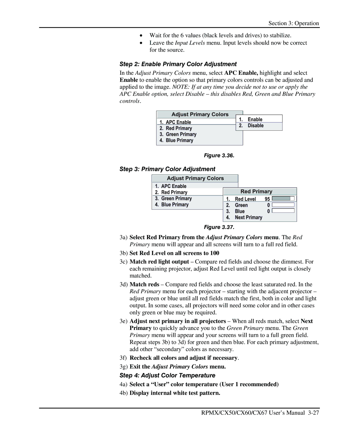
Step 3: Primary Color Adjustment
Figure 3.37.
3a) Select Red Primary from the Adjust Primary Colors menu. The Red Primary menu will appear and all screens will turn to a full red field.
3b) Set Red Level on all screens to 100
3c) Match red light output – Compare red fields and choose the dimmest. For each remaining projector, adjust Red Level until red light output is closely matched.
3d) Match reds – Compare red fields and choose the least saturated red. In the Red Primary menu for each projector – starting with the adjacent projector – adjust green or blue until all red fields match the first, both in color and light output. In some cases, all projectors will need some color and in other cases only green or blue may be required.
3e) Adjust next primary in all projectors – When all reds match, select Next Primary to quickly advance you to the Green Primary menu. The Green Primary menu will appear and your screens will turn to a full green field. Repeat steps 3b) to 3d) for green and then blue. For each primary adjustment, add other “secondary” colors as necessary.
3f) Recheck all colors and adjust if necessary.
3g) Exit the Adjust Primary Colors menu.
Step 4: Adjust Color Temperature
4a) Select a “User” color temperature (User 1 recommended)
4b) Display internal white test pattern.
RPMX/CX50/CX60/CX67 User’s Manual