Section 3: Operation
Electrical Module (EM) ' The EM is the main control unit of the projector. It is mounted independently from the PHM to the mounting tray. It is the module where all source connections are made and where the main power switch is located.
The EM contains the majority of PCB’s, such as the Control PCB, BNC Input PCB, Video Input PCB and Control
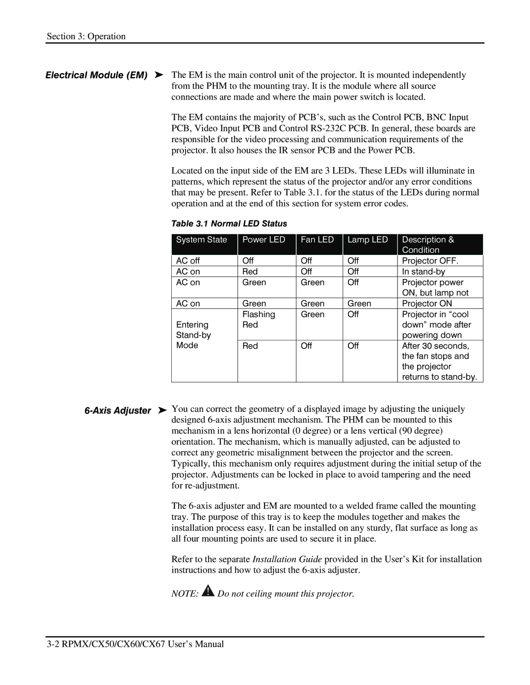
Located on the input side of the EM are 3 LEDs. These LEDs will illuminate in patterns, which represent the status of the projector and/or any error conditions that may be present. Refer to Table 3.1. for the status of the LEDs during normal operation and at the end of this section for system error codes.
Table 3.1 Normal LED Status |
|
|
|
|
|
|
| |||||
|
|
|
|
|
|
|
|
|
|
|
|
|
|
| System State |
|
| Power LED |
| Fan LED |
| Lamp LED |
| Description & |
|
|
|
|
|
|
|
|
|
|
|
| Condition |
|
|
| AC off |
|
| Off |
| Off |
| Off |
| Projector OFF. |
|
|
| AC on |
|
| Red |
| Off |
| Off |
| In |
|
|
| AC on |
|
| Green |
| Green |
| Off |
| Projector power |
|
|
|
|
|
|
|
|
|
|
|
| ON, but lamp not |
|
|
| AC on |
|
| Green |
| Green |
| Green |
| Projector ON |
|
|
|
|
|
| Flashing |
| Green |
| Off |
| Projector in “cool |
|
|
| Entering |
|
| Red |
|
|
|
|
| down” mode after |
|
|
|
|
|
|
|
|
|
|
| powering down |
| |
|
| Mode |
|
| Red |
| Off |
| Off |
| After 30 seconds, |
|
|
|
|
|
|
|
|
|
|
|
| the fan stops and |
|
|
|
|
|
|
|
|
|
|
|
| the projector |
|
|
|
|
|
|
|
|
|
|
|
| returns to |
|
mechanism in a lens horizontal (0 degree) or a lens vertical (90 degree) orientation. The mechanism, which is manually adjusted, can be adjusted to correct any geometric misalignment between the projector and the screen. Typically, this mechanism only requires adjustment during the initial setup of the projector. Adjustments can be locked in place to avoid tampering and the need for
The
Refer to the separate Installation Guide provided in the User’s Kit for installation instructions and how to adjust the
NOTE: ![]() Do not ceiling mount this projector.
Do not ceiling mount this projector.