Chapter 3 Installing Ethernet Switching Modules
Installing an Ethernet Switching Module
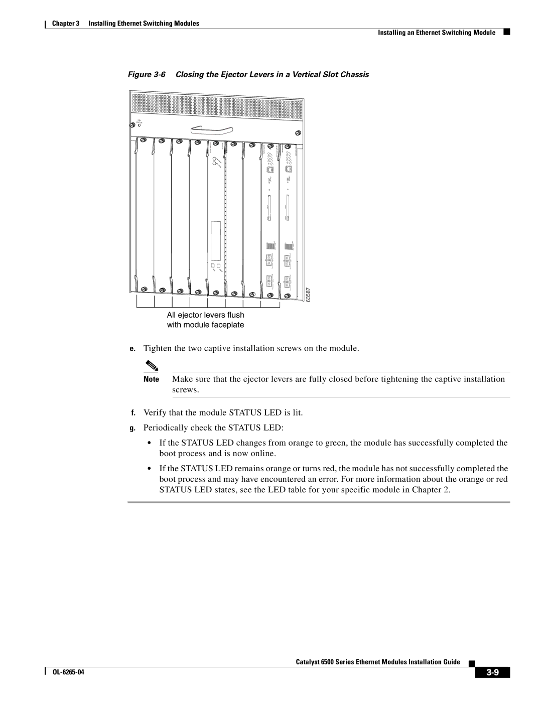
Figure 3-6 Closing the Ejector Levers in a Vertical Slot Chassis
FAN
STATUS
24PORT100FX |
STATUS
ACTIVE
N | SE |
EXT | LE |
| CT |
All ejector levers flush with module faceplate
SU PE RV ISO R2
ST |
|
ATU | |
S | S |
YST | |
CO | EM |
| |
NS | |
P | OLE |
WR | |
| MG |
RESET | |
| MT |
CON |
|
SO |
|
LE |
|
CO |
|
MODE PORT NSOLE |
|
PC |
|
MC |
|
IA |
|
EJE |
|
CT |
|
1% | 100% |
| Sw |
| itch |
| Lo |
| ad |
| POR |
| T1 |
| POR |
| T2 |
WS
SUPERVISOR2
ST |
|
ATU | |
S | S |
YST | |
CO | EM |
NS | |
P OLE | |
WR | |
RE | MG |
MT | |
SET | |
CONSOLE |
|
MODE PORT CONSOLE |
|
PCMCIA |
|
EJECT |
|
1% | 100% |
| Switch |
| Load |
| PORT1 |
| PORT2 |
63587
e.Tighten the two captive installation screws on the module.
Note Make sure that the ejector levers are fully closed before tightening the captive installation screws.
f.Verify that the module STATUS LED is lit.
g.Periodically check the STATUS LED:
•If the STATUS LED changes from orange to green, the module has successfully completed the boot process and is now online.
•If the STATUS LED remains orange or turns red, the module has not successfully completed the boot process and may have encountered an error. For more information about the orange or red STATUS LED states, see the LED table for your specific module in Chapter 2.
Catalyst 6500 Series Ethernet Modules Installation Guide
|
| ||
|
|
