Chapter 1 Catalyst 6500 Series Switch Chassis Overview
Catalyst
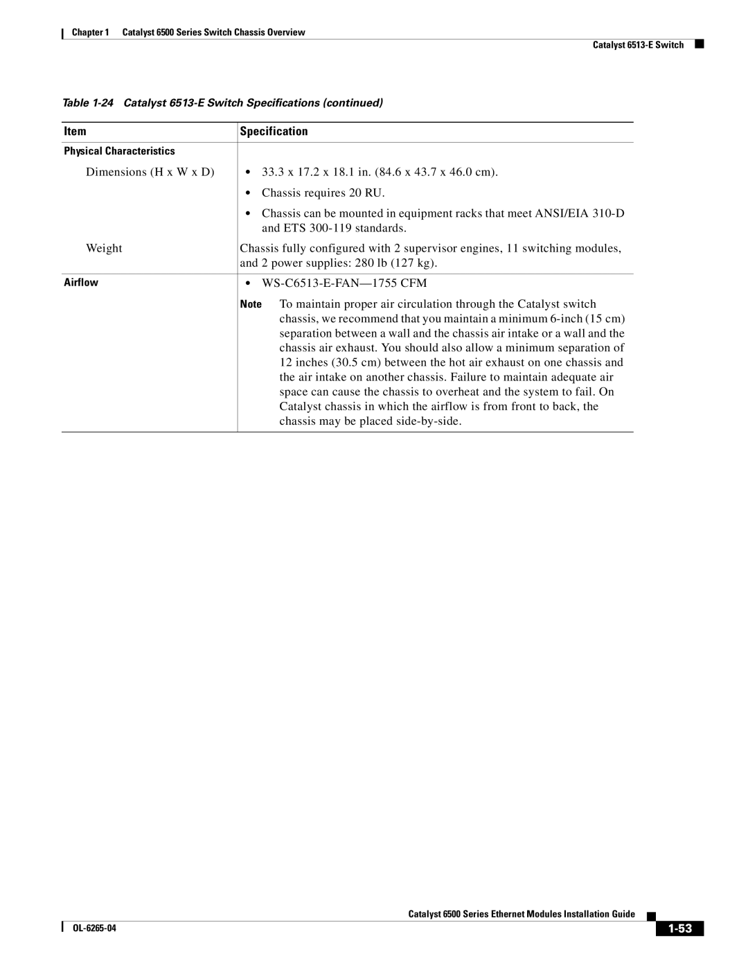
Table
Item | Specification |
|
|
Physical Characteristics |
|
Dimensions (H x W x D) | • 33.3 x 17.2 x 18.1 in. (84.6 x 43.7 x 46.0 cm). |
| • Chassis requires 20 RU. |
| • Chassis can be mounted in equipment racks that meet ANSI/EIA |
| and ETS |
Weight | Chassis fully configured with 2 supervisor engines, 11 switching modules, |
| and 2 power supplies: 280 lb (127 kg). |
|
|
Airflow | • |
| Note To maintain proper air circulation through the Catalyst switch |
| chassis, we recommend that you maintain a minimum |
| separation between a wall and the chassis air intake or a wall and the |
| chassis air exhaust. You should also allow a minimum separation of |
| 12 inches (30.5 cm) between the hot air exhaust on one chassis and |
| the air intake on another chassis. Failure to maintain adequate air |
| space can cause the chassis to overheat and the system to fail. On |
| Catalyst chassis in which the airflow is from front to back, the |
| chassis may be placed |
|
|
Catalyst 6500 Series Ethernet Modules Installation Guide
|
| ||
|
|
