Chapter 1 Catalyst 6500 Series Switch Chassis Overview
Catalyst
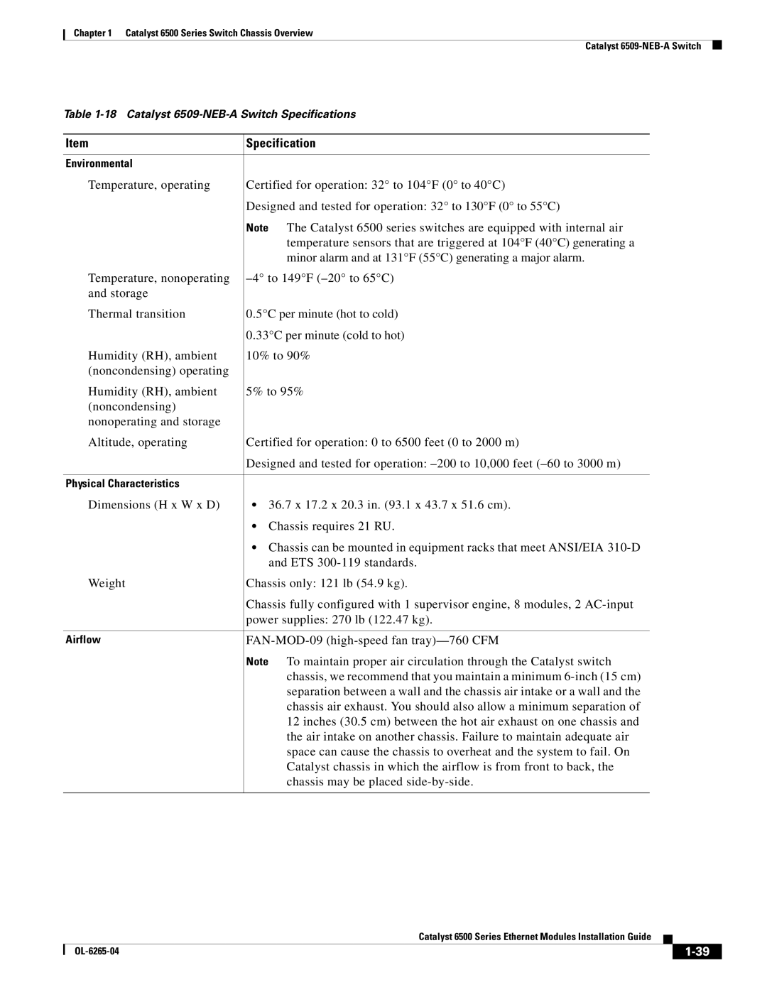
Table
Item | Specification |
|
|
Environmental |
|
Temperature, operating | Certified for operation: 32° to 104°F (0° to 40°C) |
| Designed and tested for operation: 32° to 130°F (0° to 55°C) |
| Note The Catalyst 6500 series switches are equipped with internal air |
| temperature sensors that are triggered at 104°F (40°C) generating a |
| minor alarm and at 131°F (55°C) generating a major alarm. |
Temperature, nonoperating | |
and storage |
|
Thermal transition | 0.5°C per minute (hot to cold) |
| 0.33°C per minute (cold to hot) |
Humidity (RH), ambient | 10% to 90% |
(noncondensing) operating |
|
Humidity (RH), ambient | 5% to 95% |
(noncondensing) |
|
nonoperating and storage |
|
Altitude, operating | Certified for operation: 0 to 6500 feet (0 to 2000 m) |
| Designed and tested for operation: |
|
|
Physical Characteristics |
|
Dimensions (H x W x D) | • 36.7 x 17.2 x 20.3 in. (93.1 x 43.7 x 51.6 cm). |
| • Chassis requires 21 RU. |
| • Chassis can be mounted in equipment racks that meet ANSI/EIA |
| and ETS |
Weight | Chassis only: 121 lb (54.9 kg). |
| Chassis fully configured with 1 supervisor engine, 8 modules, 2 |
| power supplies: 270 lb (122.47 kg). |
|
|
Airflow |
|
| Note To maintain proper air circulation through the Catalyst switch |
| chassis, we recommend that you maintain a minimum |
| separation between a wall and the chassis air intake or a wall and the |
| chassis air exhaust. You should also allow a minimum separation of |
| 12 inches (30.5 cm) between the hot air exhaust on one chassis and |
| the air intake on another chassis. Failure to maintain adequate air |
| space can cause the chassis to overheat and the system to fail. On |
| Catalyst chassis in which the airflow is from front to back, the |
| chassis may be placed |
|
|
Catalyst 6500 Series Ethernet Modules Installation Guide
|
| ||
|
|
