Chapter 1 Catalyst 6500 Series Switch Chassis Overview
Catalyst 6509 Switch
Table
Feature | Description |
|
|
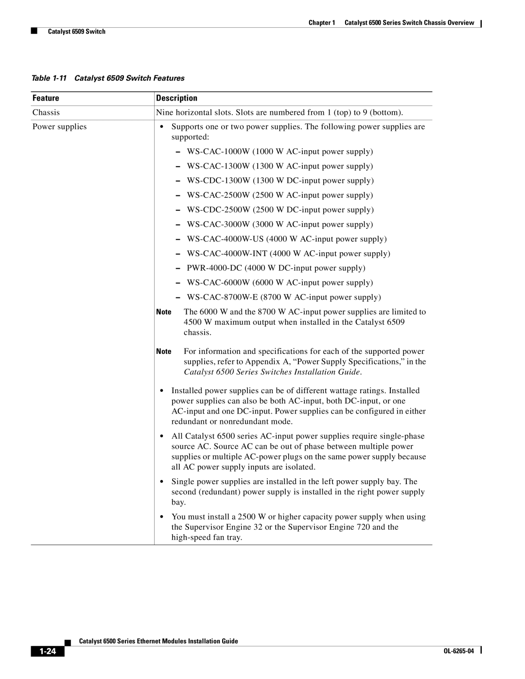
Chassis | Nine horizontal slots. Slots are numbered from 1 (top) to 9 (bottom). |
|
|
Power supplies | • Supports one or two power supplies. The following power supplies are |
| supported: |
| – |
| – |
| – |
| – |
| – |
| – |
| – |
| – |
| – |
| – |
| – |
| Note The 6000 W and the 8700 W |
| 4500 W maximum output when installed in the Catalyst 6509 |
| chassis. |
| Note For information and specifications for each of the supported power |
| supplies, refer to Appendix A, “Power Supply Specifications,” in the |
| Catalyst 6500 Series Switches Installation Guide. |
| • Installed power supplies can be of different wattage ratings. Installed |
| power supplies can also be both |
| |
| redundant or nonredundant mode. |
| • All Catalyst 6500 series |
| source AC. Source AC can be out of phase between multiple power |
| supplies or multiple |
| all AC power supply inputs are isolated. |
| • Single power supplies are installed in the left power supply bay. The |
| second (redundant) power supply is installed in the right power supply |
| bay. |
| • You must install a 2500 W or higher capacity power supply when using |
| the Supervisor Engine 32 or the Supervisor Engine 720 and the |
|
|
|
|
Catalyst 6500 Series Ethernet Modules Installation Guide
|
| |
|
