Chapter 3 Installing the Cisco AS5350XM Universal Gateway
Connecting an Alarm to the Alarm Port
Connecting an Alarm to the Alarm Port
To connect an alarm device to the alarm port, follow this procedure:
Note The alarm connector is a
Step 1 Insert the
Step 2 Strip a minimum of 1/4 in. (0.625 cm) off the wire insulation to connect the stranded wires to the alarm connector. The maximum insulation strip length is 0.31 in. (0.78 cm).
Note Connect the alarm port only to a safety
Step 3 Secure the wires to the alarm connector with the screws on the connector. See Appendix C, “Cabling Specifications,” for alarm port pinouts.
Caution The maximum tightening torque on the screws is 7
Step 4 Attach two cable ties to the chassis and connect the wires to the cable ties. (See Figure
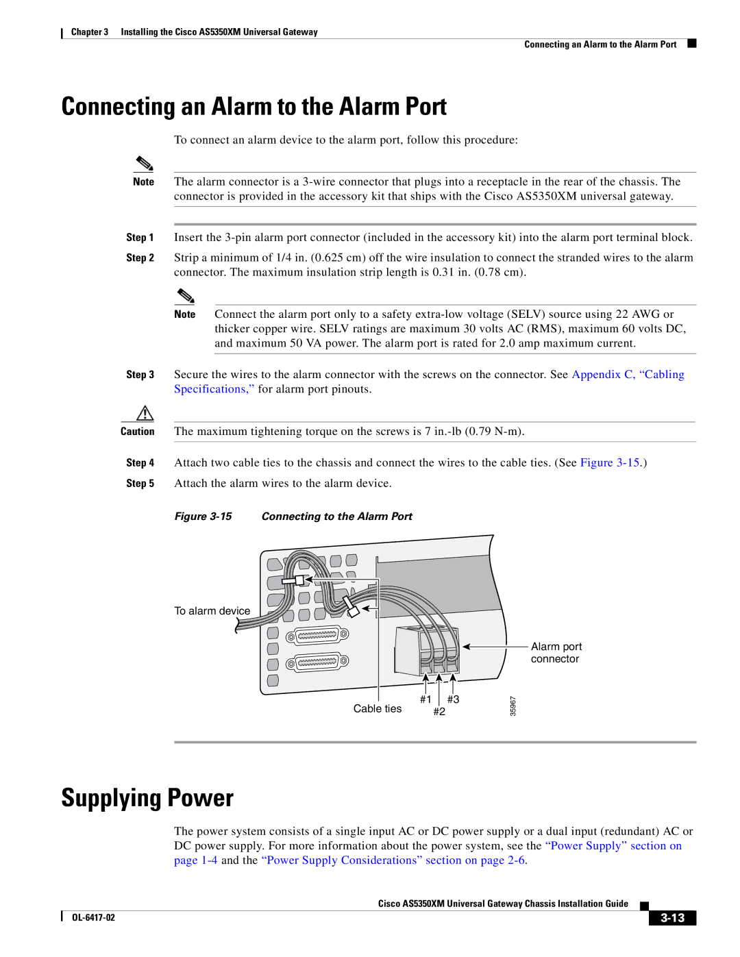
Figure 3-15 Connecting to the Alarm Port
To alarm device
|
|
|
|
|
#1 |
| #3 | ||
Cable ties | #2 |
| ||
Alarm port connector
35967
Supplying Power
The power system consists of a single input AC or DC power supply or a dual input (redundant) AC or DC power supply. For more information about the power system, see the “Power Supply” section on page
Cisco AS5350XM Universal Gateway Chassis Installation Guide
|
| ||
|
|