Appendix A Replacing Memory Components
Replacing the Compact Flash
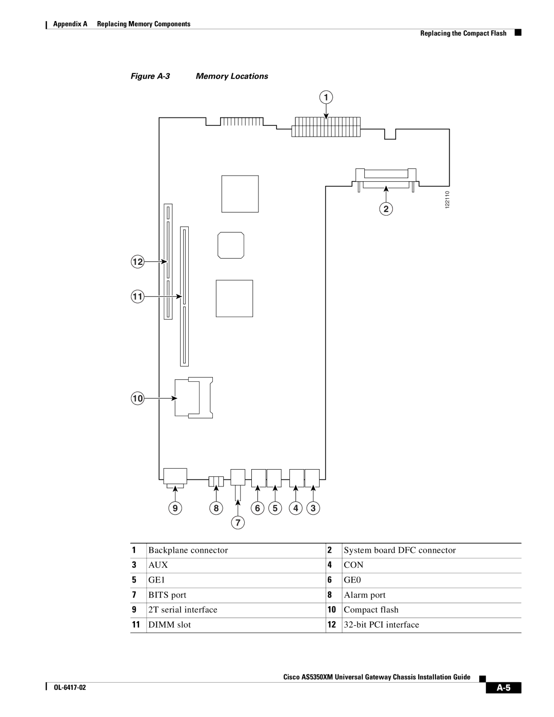
Figure A-3 Memory Locations
1
12 |
|
11 |
|
10 |
|
9 | 8 |
2
6 5 4 3
122110
7
| 1 | Backplane connector |
| 2 | System board DFC connector | ||||
|
|
|
|
|
| ||||
3 | AUX |
| 4 | CON | |||||
|
|
|
|
|
| ||||
5 | GE1 |
| 6 | GE0 | |||||
|
|
|
|
|
| ||||
7 | BITS port |
| 8 | Alarm port | |||||
|
|
|
|
|
| ||||
9 | 2T serial interface |
| 10 | Compact flash | |||||
|
|
|
|
|
| ||||
11 | DIMM slot |
| 12 | ||||||
|
|
|
|
|
|
|
|
|
|
|
|
|
| Cisco AS5350XM Universal Gateway Chassis Installation Guide |
|
|
| ||
|
|
|
|
| |||||
|
|
|
|
|
|
|
|
|
|
|
|
|
|
|
|
| |||
|
|
|
|
|
|
| |||