Appendix B Replacing the Power Supply
Removing the Old Power Supply
Figure B-6 Removing the Mounting Screw on the Redundant AC Power Supply
Mounting
screw
82078
Step 3 Turn the universal gateway so that the front panel is facing you.
Step 4 Lift the air separator out of the chassis. (See Figure
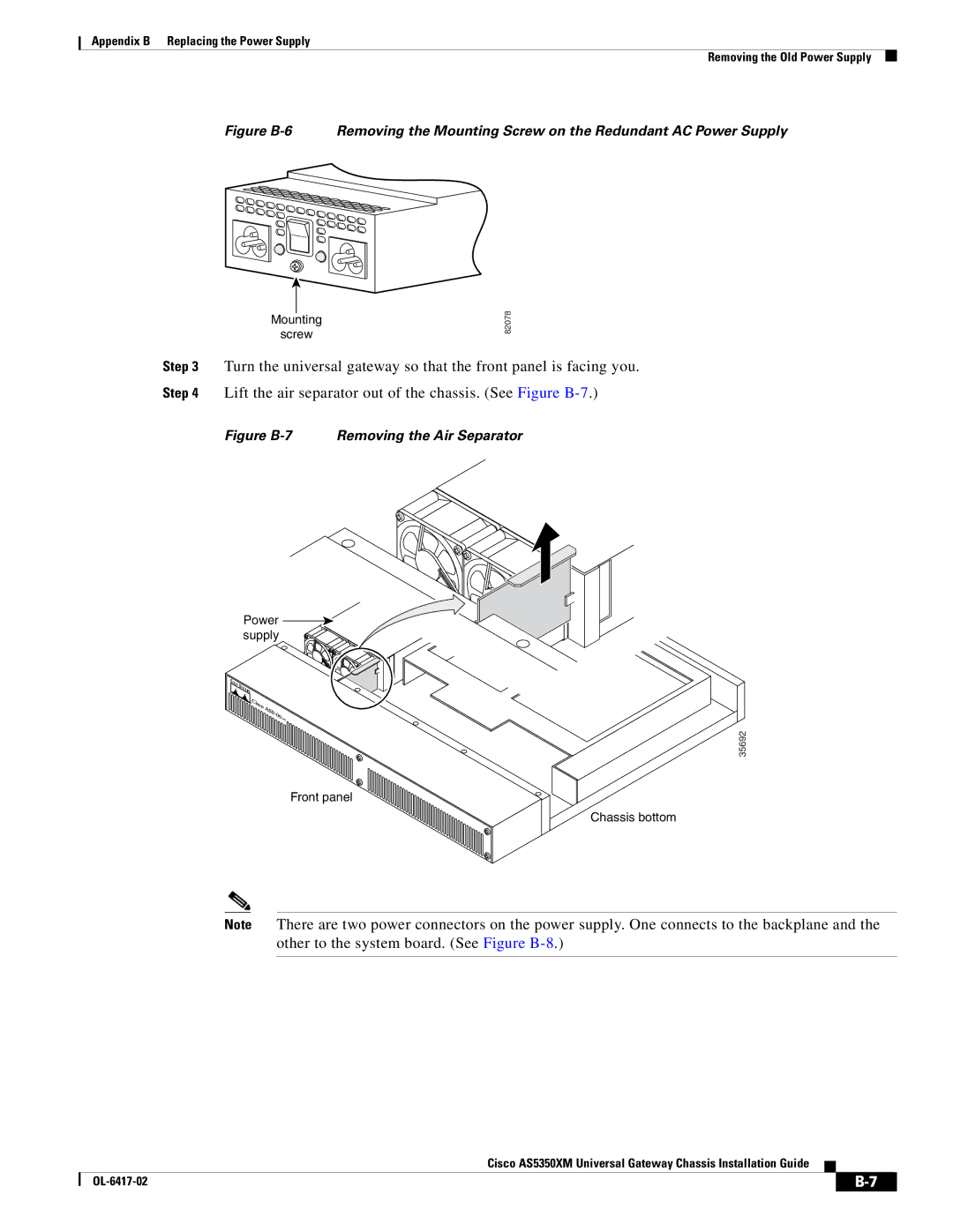
Figure B-7 Removing the Air Separator
Power supply
35692
Front panel
Chassis bottom
Note There are two power connectors on the power supply. One connects to the backplane and the other to the system board. (See Figure
Cisco AS5350XM Universal Gateway Chassis Installation Guide
| ||
|