Chapter 4 Troubleshooting
Monitoring the Environment
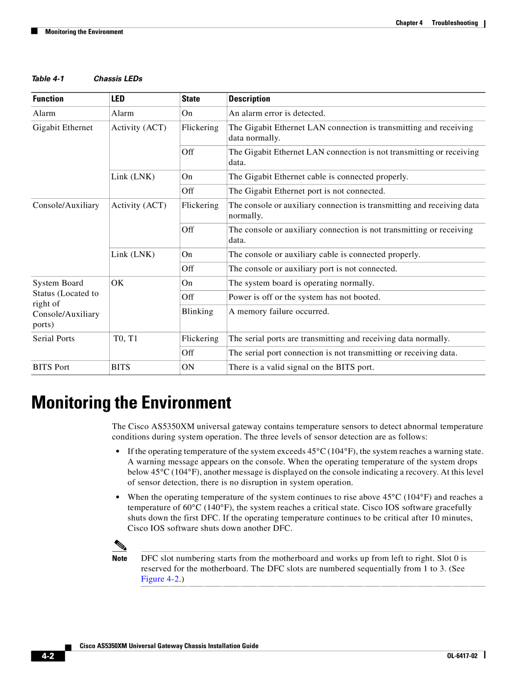
Table | Chassis LEDs |
|
| |
|
|
|
|
|
Function |
| LED | State | Description |
|
|
|
|
|
Alarm |
| Alarm | On | An alarm error is detected. |
|
|
|
|
|
Gigabit Ethernet |
| Activity (ACT) | Flickering | The Gigabit Ethernet LAN connection is transmitting and receiving |
|
|
|
| data normally. |
|
|
|
|
|
|
|
| Off | The Gigabit Ethernet LAN connection is not transmitting or receiving |
|
|
|
| data. |
|
|
|
|
|
|
| Link (LNK) | On | The Gigabit Ethernet cable is connected properly. |
|
|
|
|
|
|
|
| Off | The Gigabit Ethernet port is not connected. |
|
|
|
| |
Console/Auxiliary | Activity (ACT) | Flickering | The console or auxiliary connection is transmitting and receiving data | |
|
|
|
| normally. |
|
|
|
|
|
|
|
| Off | The console or auxiliary connection is not transmitting or receiving |
|
|
|
| data. |
|
|
|
|
|
|
| Link (LNK) | On | The console or auxiliary cable is connected properly. |
|
|
|
|
|
|
|
| Off | The console or auxiliary port is not connected. |
|
|
|
|
|
System Board |
| OK | On | The system board is operating normally. |
Status (Located to |
|
|
| |
| Off | Power is off or the system has not booted. | ||
right of |
|
| ||
|
|
|
| |
|
| Blinking | A memory failure occurred. | |
Console/Auxiliary |
| |||
|
|
| ||
ports) |
|
|
|
|
|
|
|
|
|
Serial Ports |
| T0, T1 | Flickering | The serial ports are transmitting and receiving data normally. |
|
|
|
|
|
|
|
| Off | The serial port connection is not transmitting or receiving data. |
|
|
|
|
|
BITS Port |
| BITS | ON | There is a valid signal on the BITS port. |
|
|
|
|
|
Monitoring the Environment
The Cisco AS5350XM universal gateway contains temperature sensors to detect abnormal temperature conditions during system operation. The three levels of sensor detection are as follows:
•If the operating temperature of the system exceeds 45°C (104°F), the system reaches a warning state.
A warning message appears on the console. When the operating temperature of the system drops below 45°C (104°F), another message is displayed on the console indicating a recovery. At this level of sensor detection, there is no disruption in system operation.
•When the operating temperature of the system continues to rise above 45°C (104°F) and reaches a temperature of 60°C (140°F), the system reaches a critical state. Cisco IOS software gracefully shuts down the first DFC. If the operating temperature continues to be critical after 10 minutes, Cisco IOS software shuts down another DFC.
Note DFC slot numbering starts from the motherboard and works up from left to right. Slot 0 is reserved for the motherboard. The DFC slots are numbered sequentially from 1 to 3. (See Figure
Cisco AS5350XM Universal Gateway Chassis Installation Guide
|
| |
|