Appendix B Replacing the Power Supply
Replacing the Chassis Cover
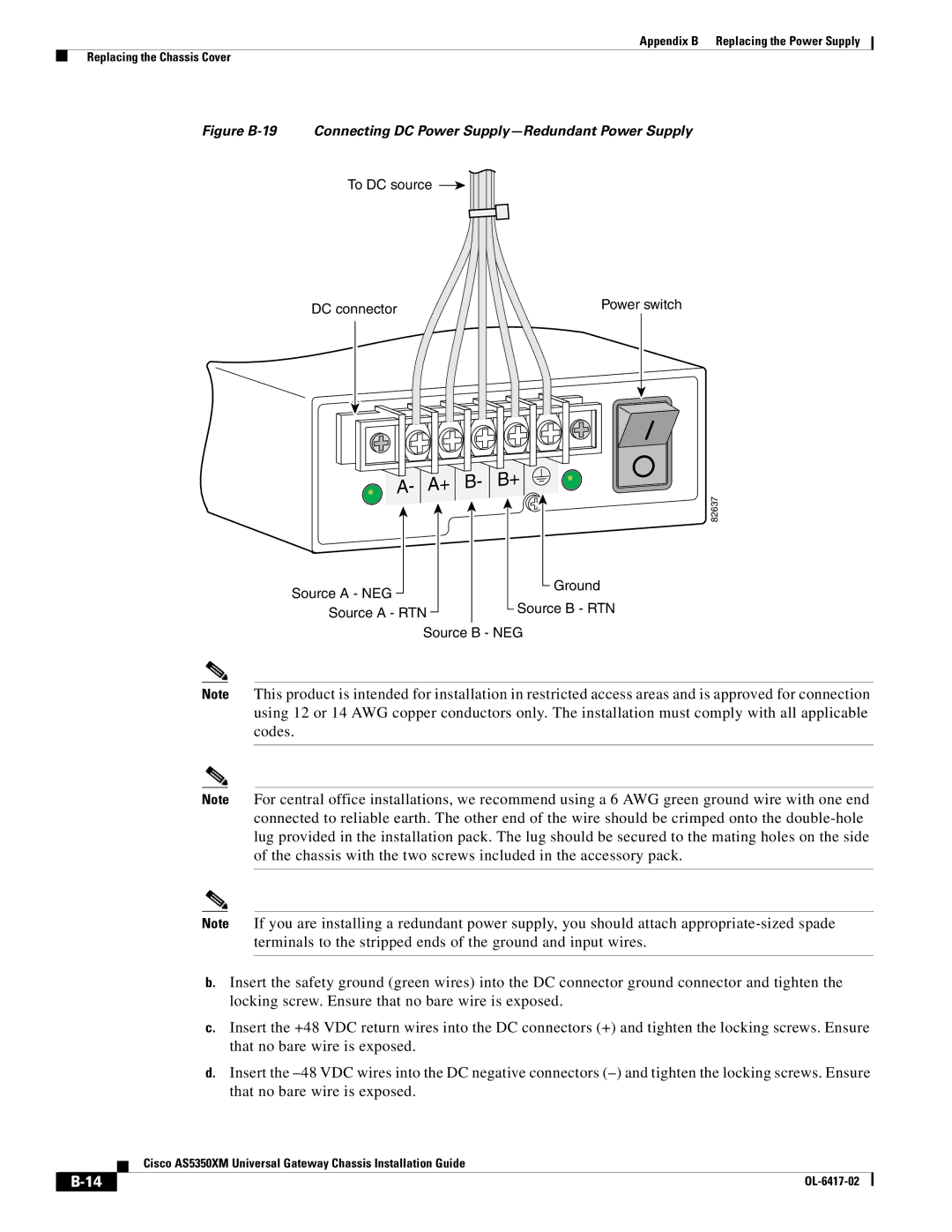
Figure B-19 Connecting DC Power Supply—Redundant Power Supply
To DC source
DC connector | Power switch |
|
Source A - NEG
82637
Ground
Source A - RTNSource B - RTN
Source B - NEG
Note This product is intended for installation in restricted access areas and is approved for connection using 12 or 14 AWG copper conductors only. The installation must comply with all applicable codes.
Note For central office installations, we recommend using a 6 AWG green ground wire with one end connected to reliable earth. The other end of the wire should be crimped onto the
Note If you are installing a redundant power supply, you should attach
b.Insert the safety ground (green wires) into the DC connector ground connector and tighten the locking screw. Ensure that no bare wire is exposed.
c.Insert the +48 VDC return wires into the DC connectors (+) and tighten the locking screws. Ensure that no bare wire is exposed.
d.Insert the
Cisco AS5350XM Universal Gateway Chassis Installation Guide
|
|
| |
|
|