Appendix B Replacing the Power Supply
Removing the Old Power Supply
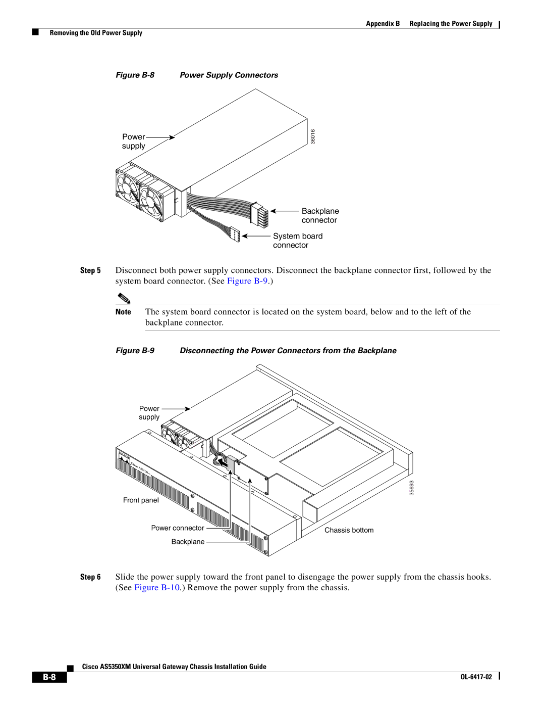
Figure B-8 Power Supply Connectors
Power supply
36016
![]()
![]()
![]()
![]() Backplane
Backplane ![]()
![]() connector
connector
System board |
connector |
Step 5 Disconnect both power supply connectors. Disconnect the backplane connector first, followed by the system board connector. (See Figure
Note The system board connector is located on the system board, below and to the left of the backplane connector.
Figure B-9 Disconnecting the Power Connectors from the Backplane
Power supply
Front panel |
Power connector |
Backplane |
35693
Chassis bottom
Step 6 Slide the power supply toward the front panel to disengage the power supply from the chassis hooks. (See Figure
Cisco AS5350XM Universal Gateway Chassis Installation Guide
|
|
| |
|
|