Cisco AS5350XM Universal Gateway Chassis Installation Guide
Cisco Systems, Inc 170 West Tasman Drive San Jose, CA
800 553-NETS Fax 408
Corporate Headquarters
Cisco AS5350XM Universal Gateway Chassis Installation Guide
Turn the television or radio antenna until the interference stops
Power Supply
Preparing to Install the Cisco AS5350XM Universal Gateway
Maintaining Safety with Electricity
C O N T E N T S
Connecting to the Network
Installing the Cisco AS5350XM Universal Gateway
Setting Up the Chassis
Connecting to a WAN
BITS Port Pinouts C-5
Alarm Port Pinouts
Overview B-1
Required Tools and Equipment B-2
Contents Cisco AS5350XM Universal Gateway Chassis Installation Guide
OL-6417-02
Troubleshooting
Preparing to Install the
Installing the
Preface
Document Conventions
Replacing the Power Supply
Cabling Specifications
italic font
Warning Definition
Warnung WICHTIGE SICHERHEITSHINWEISE
Varning! VIKTIGA SÄKERHETSANVISNINGAR
Este símbolo de aviso significa perigo. Você se encontra em uma situação em que há risco de lesões corporais. Antes de trabalhar com qualquer equipamento, esteja ciente dos riscos que envolvem os circuitos elétricos e familiarize-se com as práticas padrão de prevenção de acidentes. Use o número da declaração fornecido ao final de cada aviso para localizar sua tradução nos avisos de segurança traduzidos que acompanham o dispositivo
Document Conventions
xiii
Cisco AS5350XM Universal Gateway Chassis Installation Guide
OL-6417-02
Cisco.com
Obtaining Documentation
Product Documentation DVD
Documentation Feedback
Ordering Documentation
Cisco Product Security Overview
Reporting Security Problems in Cisco Products
Emergencies - security-alert@cisco.com
Cisco Technical Support & Documentation Website
Submitting a Service Request
Obtaining Technical Assistance
http//tools.cisco.com/RPF/register/register.do
Obtaining Additional Publications and Information
Definitions of Service Request Severity
xviii
Internet Protocol Journal is a quarterly journal published by Cisco Systems for engineering professionals involved in designing, developing, and operating public and private internets and intranets. You can access the Internet Protocol Journal at this URL
Obtaining Additional Publications and Information
Cisco AS5350XM Universal Gateway Chassis Installation Guide
OL-6417-02
Overview
Chassis Components, page Dial Feature Cards DFCs, page
Power Supply, page Chassis Specifications, page
Chassis Components
Figure 1-1 Cisco AS5350XM Universal Gateway Front Panel
Product Serial Number Location
Cisco AS5350XM Universal Gateway Chassis Installation Guide
Figure 1-2 Cisco AS5350XM Universal Gateway Rear Panel
Cisco Product Identification Tool
Dial Feature Cards DFCs
http//tools.cisco.com/Support/CPI/index.do
Power Supply
Chassis Specifications
section on page
See the Regulatory Compliance and Safety
Cisco.com. See the “Obtaining Documentation”
Chassis Specifications continued
Cisco AS5350XM Universal Gateway Chassis Installation Guide
Chapter 1 Overview Chassis Specifications
OL-6417-02
Maintaining Safety with Electricity
Preparing to Install the Cisco AS5350XM Universal Gateway
Safety Recommendations
Safety Recommendations, page Required Tools and Equipment, page
Preventing Electrostatic Discharge Damage
Required Tools and Equipment
Preparing to Connect to a Network
Console and Auxiliary Ports
Ethernet Connections
Console Port
BITS Port
Alarm Port
2T Serial Ports
Auxiliary Port
Power Supply Considerations
Setting Up the Chassis, page Connecting to the Network, page
Installing the Cisco AS5350XM Universal Gateway
Setting Up the Chassis
Connecting to the Console and Auxiliary Ports, page
Setting the Chassis on a Desktop
Attaching the Rubber Feet
Rack-Mounting the Chassis
Figure 3-1 Attaching the Rubber Feet
Required Tools and Equipment
Attaching the Brackets
Installing in a Rack
Connecting the Chassis Ground
Connecting to the Network
Connecting to an Ethernet Network
Connecting to a WAN
Figure 3-6 Connecting to an Ethernet Hub 10/100BASE-T Shown
Straight-through RJ-45-to-RJ-45 cable
Figure 3-7 Connecting a 2-Port or 4-Port DFC to an RJ-45 T1 Jack
Figure 3-8 Connecting an 8-Port DFC to an RJ-45 T1 Jack
RJ-45 jack
Figure 3-9 Connecting a 2-Port or 4-Port DFC to an RJ-45 Jack
RJ-45 jack E1 cable
Figure 3-11 Connecting to a CSU/DSU
3-10
Figure 3-10 Connecting an 8-Port DFC to an RJ-45 Jack
Chapter 3 Installing the Cisco AS5350XM Universal Gateway
Connecting to the Console Port
Connecting to the Console and Auxiliary Ports
3-11
Connecting a Modem to the Auxiliary Port
Connecting a Signal Generator to the BITS Port
3-12
Supplying Power
Connecting an Alarm to the Alarm Port
3-13
Connecting the AC Power Cord
3-14
Figure 3-16 Connecting the AC Power Cord
Wiring the DC Power Supply
3-15
Power switch
Power switch
3-16
Figure 3-18 DC Power Supply Connections-Single Power Supply
DC connector
Figure 3-19 DC Power Supply Connections-Redundant Power Supply
3-17
Power switch
Appendix B, “Replacing the Power Supply”
Where to Go Next
Chapter 4, “Troubleshooting”
Appendix C, “Cabling Specifications”
LEDs
Troubleshooting
Troubleshooting Network Interfaces, page Replacing the Fan Tray, page
LEDs, page Monitoring the Environment, page
Monitoring the Environment
Chassis LEDs
Displaying the Environment Status
Power Supply
Cisco AS5350XM Universal Gateway Chassis Installation Guide
Replacing the Fan Tray
Troubleshooting Network Interfaces
Removing the Fan Tray
Figure 4-3 Cisco AS5350XM Front Panel
Figure 4-4 Loosen Fan Tray Screws
Cisco AS5350XM Universal Gateway Chassis Installation Guide
Figure 4-6 Fan Tray Power Connector Disconnecting from the Receptacle
Chapter 4 Troubleshooting Replacing the Fan Tray
Figure 4-5 Pulling the Edge of the Fan Tray
Installing the Fan Tray
Cisco AS5350XM Universal Gateway Chassis Installation Guide
Figure 4-9 Sliding the Fan Tray Power Connector into the Receptacle
Chapter 4 Troubleshooting Replacing the Fan Tray
Figure 4-8 Inserting the Metal Tabs into the Slots
4-10
Getting Help
Figure 4-10 Tightening Fan Tray Screws
Removing the Chassis Cover
Safety Recommendations
Replacing Memory Components
Required Tools
Chassis Cover Removal
Figure A-2 Removing the Chassis Cover
Cisco AS5350XM Universal Gateway Chassis Installation Guide
Figure A-1 Removing the Chassis Cover Screws
Appendix A Replacing Memory Components Removing the Chassis Cover
Replacing the Compact Flash
6 5 4
Required Tools and Equipment
Replacing DIMMs
Replacing the DIMM
Figure A-4 Removing and Replacing the DIMM
Replacing the Chassis Cover
Required Tools and Equipment
Chassis Cover Replacement
A-10
Figure A-7 Cisco AS5350XM Chassis
Removing the Old Power Supply, page B-6
Replacing the Power Supply
Safety Recommendations, page B-1
Installing the Power Supply, page B-9
Required Tools and Equipment
Removing the Chassis Cover
Figure B-1 DC Power Supply Connections-Single Power Supply
Page
Figure B-3 Removing the Chassis Cover Screws
Appendix B Replacing the Power Supply Removing the Chassis Cover
Cisco AS5350XM Universal Gateway Chassis Installation Guide
Figure B-4 Removing the Chassis Cover
Removing the Old Power Supply
Page
Figure B-8 Power Supply Connectors
Figure B-9 Disconnecting the Power Connectors from the Backplane
Installing the Power Supply
Figure B-11 Inserting the Power Supply in the Chassis
B-10
Figure B-12 Reconnecting the Power Cables to the Backplane
Replacing the Chassis Cover
B-11
Figure B-13 Replacing the Air Separator
Power Ratings Label for AC Power Supply
B-12
Power Ratings Label for DC Power Supply
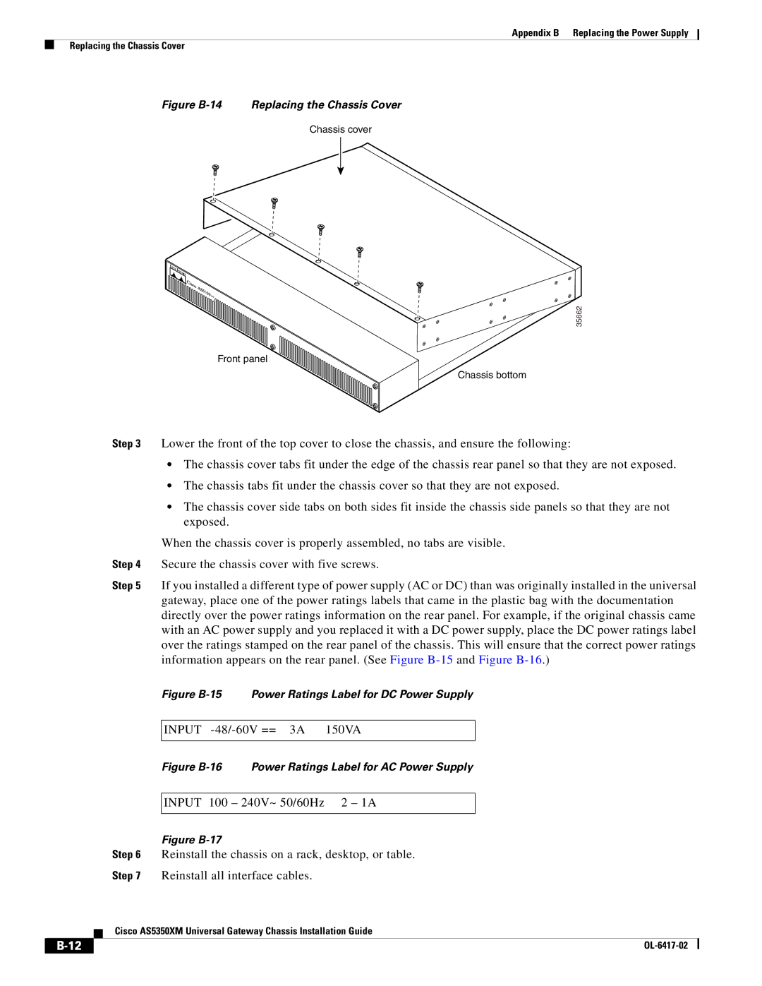
Figure B-14 Replacing the Chassis Cover
B-13
Figure B-18 Connecting DC Power Supply-Single Power Supply
B-14
Figure B-19 Connecting DC Power Supply-Redundant Power Supply
The internal power supply fan should power up
B-15
Step 9 Power up the universal gateway
Appendix B Replacing the Power Supply Replacing the Chassis Cover
Cisco AS5350XM Universal Gateway Chassis Installation Guide
B-16
Appendix B Replacing the Power Supply Replacing the Chassis Cover
OL-6417-02
Console and Auxiliary Port Cables and Pinouts
Cabling Specifications
Alarm Port Pinouts, page C-5 Bantam Jack Port Pinouts, page C-5
A P P E N D I X C
Identifying a Rollover Cable
Console Port Cables and Pinouts
Console Port DTE
Ethernet Port Pinouts
Auxiliary Port Cables and Pinouts
BITS Port Pinouts
Alarm Port Pinouts
Bantam Jack Port Pinouts
Cisco AS5350XM Universal Gateway Chassis Installation Guide
Appendix C Cabling Specifications Bantam Jack Port Pinouts
OL-6417-02
I N D E
Numerics
IN-1
environment monitoring
IN-2
error messages, compact flash
environment status, displaying
IN-3
IN-4
IN-5
Index
IN-6
Cisco AS5350XM Universal Gateway Chassis Installation Guide
OL-6417-02