Appendix B Replacing the Power Supply
Installing the Power Supply
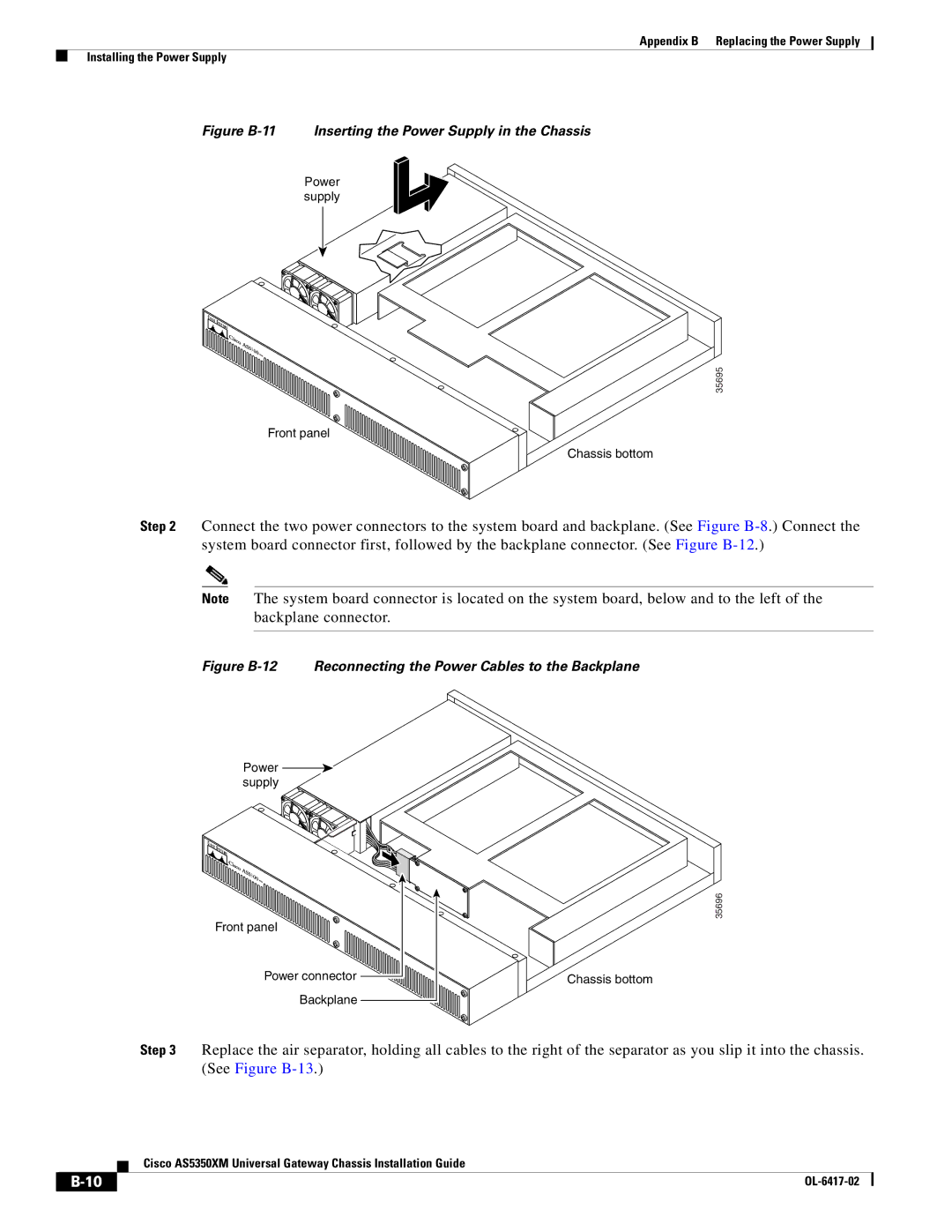
Figure B-11 Inserting the Power Supply in the Chassis
Power supply
![]()
![]() 3
3
35695
Front panel
Chassis bottom
Step 2 Connect the two power connectors to the system board and backplane. (See Figure
Note The system board connector is located on the system board, below and to the left of the backplane connector.
Figure B-12 Reconnecting the Power Cables to the Backplane
Power supply
3 |
Front panel |
Power connector |
Backplane |
35696
Chassis bottom
Step 3 Replace the air separator, holding all cables to the right of the separator as you slip it into the chassis. (See Figure
Cisco AS5350XM Universal Gateway Chassis Installation Guide
|
|
| |
|
|