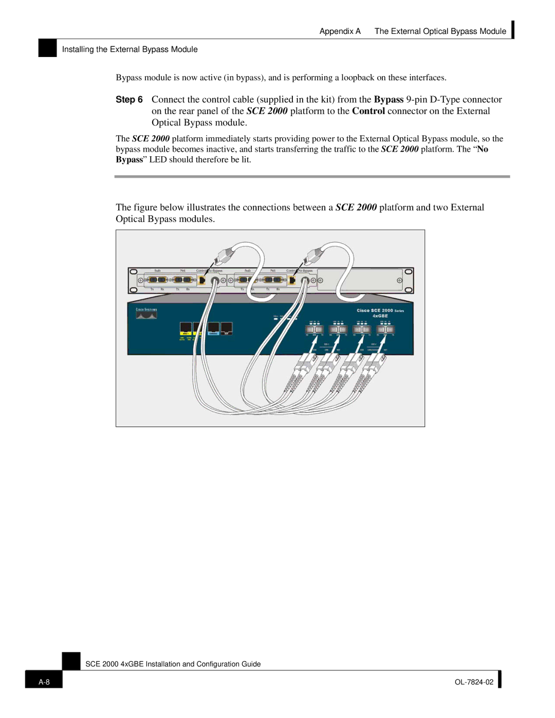
SCE 2000 4xGBE specifications
The Cisco Systems SCE 2000 4xGBE is a robust solution designed to optimize IP networks and enhance service delivery. As a member of Cisco's Service Control Engine (SCE) product line, this device is particularly suited for service providers looking to manage network traffic, improve service quality, and provide a suite of advanced management features.One of the standout features of the SCE 2000 is its ability to process and analyze network traffic in real-time. This capability allows operators to gain insights into user behavior, application usage, and overall network performance. By utilizing deep packet inspection technology, the SCE 2000 can identify different types of traffic, enabling network managers to enforce policies and prioritize critical applications effectively.
In terms of interface capabilities, the SCE 2000 offers four 1 Gigabit Ethernet (GbE) ports. This versatility allows for easy integration into existing network infrastructure while ensuring ample bandwidth for data transfer. The device supports both IPv4 and IPv6 protocols, making it future-proof and suitable for evolving network demands.
One of the significant technologies employed by the SCE 2000 is Service Level Agreement (SLA) management. This feature ensures that service providers can meet their commitments to customers by monitoring performance metrics such as latency, jitter, and packet loss. The ability to generate reports based on SLA compliance allows for better customer engagement and transparency.
Additionally, the SCE 2000 facilitates dynamic resource allocation, enabling service providers to adapt network resources based on current demand. This elasticity is crucial in managing peak loads and ensuring a seamless user experience. Furthermore, the device’s support for Quality of Service (QoS) policies ensures that critical applications receive the necessary bandwidth and resources dedicated to maintaining operational efficiency.
The SCE 2000 also emphasizes security with features such as intrusion detection and prevention capabilities, helping protect the integrity of the network. This combination of performance monitoring, traffic management, and security makes the SCE 2000 an invaluable tool for service providers.
In conclusion, the Cisco Systems SCE 2000 4xGBE is a powerful network management solution that excels in providing real-time traffic management, SLA compliance, and security features. Its capabilities make it an essential component for service providers aiming to optimize their networks while delivering high-quality services to their customers.

