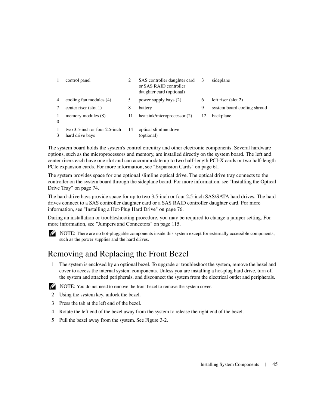
1 | control panel | 2 | SAS controller daughter card | 3 | sideplane |
|
|
| or SAS RAID controller |
|
|
|
|
| daughter card (optional) |
|
|
4 | cooling fan modules (4) | 5 | power supply bays (2) | 6 | left riser (slot 2) |
7 | center riser (slot 1) | 8 | battery | 9 | system board cooling shroud |
1 | memory modules (8) | 11 | heatsink/microprocessor (2) | 12 | backplane |
0 |
|
|
|
|
|
1 | two | 14 | optical slimline drive |
|
|
3 | hard drive bays |
| (optional) |
|
|
The system board holds the system's control circuitry and other electronic components. Several hardware options, such as the microprocessors and memory, are installed directly on the system board. The left and center risers each have one slot and can accommodate up to two
The system provides space for one optional slimline optical drive. The optical drive tray connects to the controller on the system board through the sideplane board. For more information, see "Installing the Optical Drive Tray" on page 74.
The
During an installation or troubleshooting procedure, you may be required to change a jumper setting. For more information, see "Jumpers and Connectors" on page 115.
NOTE: There are no
Removing and Replacing the Front Bezel
1The system is enclosed by an optional bezel. To upgrade or troubleshoot the system, remove the bezel and cover to access the internal system components. Unless you are installing a
NOTE: You do not need to remove the front bezel to remove the system cover.
2Using the system key, unlock the bezel.
3Press the tab at the left end of the bezel.
4Rotate the left end of the bezel away from the system to release the right end of the bezel.
5Pull the bezel away from the system. See Figure
Installing System Components
45